8.6 Applications of elastic behaviour of materials
The elastic behaviour of materials plays an important role in everyday life. All engineering designs require precise knowledge of the elastic behaviour of materials. For example while designing a building, the structural design of the columns, beams and supports require knowledge of strength of materials used.
Elasticity helps us understand how various materials respond to forces. This knowledge explains why beams can support heavy loads without permanently bending, why bridges remain stable under the weight of vehicles, and why pillars in buildings withstand enormous compressive forces without permanent deformation. The key to these phenomena lies in the elastic behaviour of materials, which allows them to deform under stress and return to their original shape once the force is removed-as long as the force is within the material’s elastic limit.
For example, when a heavy vehicle passes over a steel bridge, the bridge beams slightly bend under the load but immediately return to their original shape after the vehicle passes. Similarly, concrete pillars supporting buildings slightly compress under weight but regain their original form once the load is removed. However, if the load exceeds the elastic limit, the material experiences plastic deformation, resulting in permanent damage or structural failure.
Understanding elasticity through concepts like Hooke’s Law, elastic moduli and elastic limit helps engineers predict how materials such as steel beams, concrete pillars, suspension cables, and support columns will behave under load. By carefully analysing these properties, engineers ensure bridges, buildings, and infrastructure remain stable, safe, and durable, avoiding catastrophic failures.
Design of Cranes and Metallic Ropes
Cranes used to lift heavy loads (like at construction sites) use thick metallic ropes.
The Problem: We need to ensure the stress on the rope doesn’t exceed the elastic limit of the material (usually steel).
The Math: If a crane needs to lift a load of mass \(M\), the force is \(M g\). To ensure safety, we calculate the required area of cross-section \(\boldsymbol{A}\) :
\(
\text { Stress }=\frac{M g}{A}<\text { Yield Strength of Steel }
\)
Safety Factor: Engineers usually design the rope to withstand 10 times the actual intended load to account for sudden jerks or wear and tear.
Maximum Height of a Mountain on Earth
Elasticity explains why we don’t have mountains much taller than Mt. Everest (approx. 9 km).
The Logic: At the base of a mountain, the pressure (stress) is \(\rho g h\) (where \(\rho\) is the density of rock and \(h\) is height).
The Constraint: This stress must be less than the Elastic Limit (Yield Strength) of the rocks.
Calculation: For typical rock, the yield strength is about \(3 \times 10^8 \mathrm{~N} / \mathrm{m}^2\).
\(
h<\frac{\text { Yield Strength }}{\rho g} \approx \frac{3 \times 10^8}{3000 \times 10} \approx 10,000 \text { meters }(10 \mathrm{~km})
\)
If a mountain were taller, the rocks at the base would “flow” like a plastic liquid under the immense weight.
Construction of Bridges and Buildings
Bridges and buildings are designed to withstand enormous stresses due to their own weight, external forces such as wind and earthquakes, and the loads they carry. To prevent failure, engineers consider elastic limits, ensuring materials like steel and concrete do not undergo permanent deformation.
Design of Beams
Steel beams are commonly used in construction due to their high Young’s modulus, which means they can bear large forces without significant elongation.
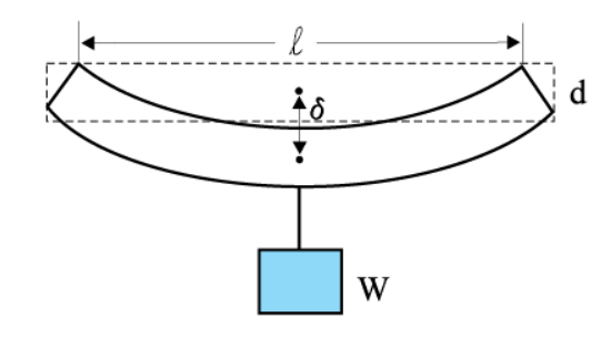
The sagging of a beam (\(\delta\))due to load is calculated using the equation:
\(
\delta=\frac{W l^3}{4 b d^3 Y}
\)
where:
\(W=\) Load on the beam
\(l=\) Length of the beam
\(b=\) Breadth of the beam
\(d=\) Depth of the beam
\(Y=\) Young’s modulus of the material
This formula helps engineers design beams that minimise bending while remaining lightweight and cost-effective.
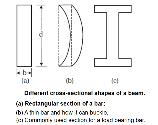
For a given material, increasing a beam’s depth \(d\) is more effective in reducing bending than increasing its breadth \(b\). However, excessive depth can cause the beam to deform sideways under load, a phenomenon known as buckling.
To address this, engineers commonly use an I-beam, a cross-sectional shape designed to provide sufficient depth for strength, a broad surface for stability, and minimal weight. I-beam maximises strength while minimising weight. This shape significantly reduces the risk of buckling, allowing beams to safely carry heavy loads without unnecessary use of material.
We see that to reduce the bending for a given load, one should use a material with a large Young’s modulus \(Y\). For a given material, increasing the depth \(d\) rather than the breadth \(b\) is more effective in reducing the bending, since \(\delta\) is proportional to \(d^{-3}\) and only to \(b^{-1}\) (of course the length \(I\) of the span should be as small as possible). But on increasing the depth, unless the load is exactly at the right place (difficult to arrange in a bridge with moving traffic), the deep bar may bend as shown in Fig. (b). This is called buckling. To avoid this, a common compromise is the cross-sectional shape shown in Fig. (c). This section provides a large loadbearing surface and enough depth to prevent bending. This shape reduces the weight of the beam without sacrificing the strength and hence reduces the cost.
Design of Pillars
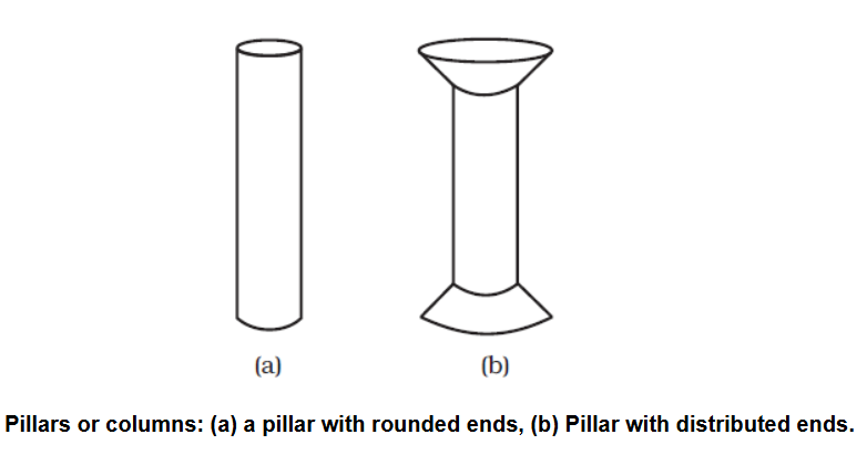
The use of pillars or columns is also very common in buildings and bridges. A pillar with rounded ends as shown in Figure (a) supports less load than that with a distributed shape at the ends [Figure (b)]. The precise design of a bridge or a building has to take into account the conditions under which it will function, the cost and long period, reliability of usable material, etc.
The shape and design of pillars significantly influence their strength and stability. Pillars support heavy vertical loads and must be carefully designed to distribute these forces evenly, minimising stress concentrations.
Uniform cylindrical pillars:
Pillars with uniform cross-sectional areas throughout are simple to build but may experience higher stress at the ends due to concentrated loads, increasing the risk of structural failure.
Pillars with broader ends:
Pillars designed with broader bases at both ends are structurally superior. These expanded ends distribute the compressive load over a larger area, reducing stress concentrations, enhancing stability, and increasing the overall strength and safety of the structure.
The answer to the question why the maximum height of a mountain on earth is \(\sim 10 \mathrm{~km}\) can also be provided by considering the elastic properties of rocks. A mountain base is not under uniform compression and this provides some shearing stress to the rocks under which they can flow. The stress due to all the material on the top should be less than the critical shearing stress at which the rocks flow.
At the bottom of a mountain of height \(h\), the force per unit area due to the weight of the mountain is \(h \rho g\) where \(\rho\) is the density of the material of the mountain and \(g\) is the acceleration due to gravity. The material at the bottom experiences this force in the vertical direction, and the sides of the mountain are free. Therefore, this is not a case of pressure or bulk compression. There is a shear component, approximately \(h \rho g\) itself. Now the elastic limit for a typical rock is \(30 \times 10^7 \mathrm{~N} \mathrm{~m}^{-2}\). Equating this to \(h \rho g\), with
\(
\begin{aligned}
\rho= & 3 \times 10^3 \mathrm{~kg} \mathrm{~m}^{-3} \text { gives } \\
& h \rho g=30 \times 10^7 \mathrm{~N} \mathrm{~m}^{-2} . \\
h & =30 \times 10^7 \mathrm{~N} \mathrm{~m}^{-2} /\left(3 \times 10^3 \mathrm{~kg} \mathrm{~m}^{-3} \times 10 \mathrm{~m} \mathrm{~s}^{-2}\right) \\
& =10 \mathrm{~km}
\end{aligned}
\)
which is more than the height of Mt. Everest!