JEE PYQs MCQs (Rotational Motion)
SUMMARY
- Ideally, a rigid body is one for which the distances between different particles of the body do not change, even though there are forces on them.
- A rigid body fixed at one point or along a line can have only rotational motion. A rigid body not fixed in some way can have either pure translational motion or a combination of translational and rotational motions.
- In rotation about a fixed axis, every particle of the rigid body moves in a circle which lies in a plane perpendicular to the axis and has its centre on the axis. Every Point in the rotating rigid body has the same angular velocity at any instant of time.
- In pure translation, every particle of the body moves with the same velocity at any instant of time.
- Angular velocity is a vector. Its magnitude is \(\omega=d \theta / d t\) and it is directed along the axis of rotation. For rotation about a fixed axis, this vector \(\omega\) has a fixed direction.
- The vector or cross product of two vector \(a\) and \(b\) is a vector written as \(a \times b\). The magnitude of this vector is \(a b \sin \theta\) and its direction is given by the right handed screw or the right hand rule.
- The linear velocity of a particle of a rigid body rotating about a fixed axis is given by \(v = \omega \times r\), where \(r\) is the position vector of the particle with respect to an origin along the fixed axis. The relation applies even to more general rotation of a rigid body with one point fixed. In that case \(r\) is the position vector of the particle with respect to the fixed point taken as the origin.
- The centre of mass of a system of \(n\) particles is defined as the point whose position vector is
\(
R =\frac{\sum m_i r _i}{M}
\) - Velocity of the centre of mass of a system of particles is given by \(V = P / M\), where \(P\) is the linear momentum of the system. The centre of mass moves as if all the mass of the system is concentrated at this point and all the external forces act at it. If the total external force on the system is zero, then the total linear momentum of the system is constant.
- The angular momentum of a system of \(n\) particles about the origin is
\(
L =\sum_{i=1}^n r _i \times p _i
\)
The torque or moment of force on a system of \(n\) particles about the origin is
\(
\tau =\sum_{i=1}^n r _i \times F _i
\)
The force \(F _i\) acting on the \(i^{\text {th }}\) particle includes the external as well as internal forces. Assuming Newton’s third law of motion and that forces between any two particles act along the line joining the particles, we can show \(\tau _{\text {int }}= 0\) and
\(
\frac{d L }{d t}= \tau _{e x t}
\) - A rigid body is in mechanical equilibrium if
(a) it is in translational equilibrium, i.e., the total external force on it is zero : \(\sum F _i= 0\), and
(b) it is in rotational equilibrium, i.e. the total external torque on it is zero :
\(
\sum \tau _i=\sum r _i \times F _i= 0
\) - The centre of gravity of an extended body is that point where the total gravitational torque on the body is zero.
- The moment of intertia of a rigid body about an axis is defined by the formula \(I=\sum m_i r_i^2\) where \(r_i\) is the perpendicular distance of the \(i\) th point of the body from the axis. The kinetic energy of rotation is \(K=\frac{1}{2} I \omega^2\).
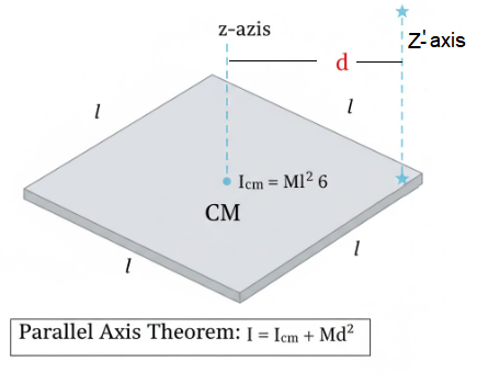
- The theorem of parallel axes: \(I_z^{\prime}=I_z+M a^2\), allows us to determine the moment of intertia of a rigid body about an axis as the sum of the moment of inertia of the body about a parallel axis through its centre of mass and the product of mass and square of the perpendicular distance between these two axes.
- Rotation about a fixed axis is directly analogous to linear motion in respect of kinematics and dynamics.
- For a rigid body rotating about a fixed axis (say, \(z\)-axis) of rotation, \(L_{ z }=I \omega\), where \(I\) is the moment of inertia about \(z\)-axis. In general, the angular momentum \(L\) for such a body is not along the axis of rotation. Only if the body is symmetric about the axis of rotation, \(L\) is along the axis of rotation. In that case, \(| L |=L_z=I \omega\). The angular acceleration of a rigid body rotating about a fixed axis is given by \(I \alpha=\tau\). If the external torque \(\tau\) acting on the body is zero, the component of angular momentum about the fixed axis (say, \(z\)-axis), \(L_z(=I \omega)\) of such a rotating body is constant.
- For rolling motion without slipping \(v_{c m}=R \omega\), where \(v_{c m}\) is the velocity of translation (i.e. of the centre of mass), \(R\) is the radius and \(m\) is the mass of the body. The kinetic energy of such a rolling body is the sum of kinetic energies of translation and rotation:
\(
K=\frac{1}{2} m v_{c m}^2+\frac{1}{2} I \omega^2
\)
Quiz Summary
0 of 72 Questions completed
Questions:
Information
You have already completed the quiz before. Hence you can not start it again.
Quiz is loading…
You must sign in or sign up to start the quiz.
You must first complete the following:
Results
Results
0 of 72 Questions answered correctly
Your time:
Time has elapsed
You have reached 0 of 0 point(s), (0)
Earned Point(s): 0 of 0, (0)
0 Essay(s) Pending (Possible Point(s): 0)
Categories
- Not categorized 0%
- 1
- 2
- 3
- 4
- 5
- 6
- 7
- 8
- 9
- 10
- 11
- 12
- 13
- 14
- 15
- 16
- 17
- 18
- 19
- 20
- 21
- 22
- 23
- 24
- 25
- 26
- 27
- 28
- 29
- 30
- 31
- 32
- 33
- 34
- 35
- 36
- 37
- 38
- 39
- 40
- 41
- 42
- 43
- 44
- 45
- 46
- 47
- 48
- 49
- 50
- 51
- 52
- 53
- 54
- 55
- 56
- 57
- 58
- 59
- 60
- 61
- 62
- 63
- 64
- 65
- 66
- 67
- 68
- 69
- 70
- 71
- 72
- Current
- Review
- Answered
- Correct
- Incorrect
- Question 1 of 72
1. Question
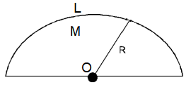
A rod of linear mass density ‘ \(\lambda\) ‘ and length ‘ \(L\) ‘ is bent to form a ring of radius ‘ \(R\) ‘. Moment of inertia of ring about any of its diameter is. [JEE Main 2025 (Online) 8th April Evening Shift]
CorrectIncorrectHint
(a) Step 1: Relate rod properties to ring properties
The total mass ( \(M\) ) of the rod (and thus the ring) is the linear mass density ( \(\lambda\) ) multiplied by the length \((L)\) :
\(
M=\lambda L
\)
The length of the rod forms the circumference of the ring, so:
\(
L=2 \pi R
\)
We can express the radius ( \(R\) ) in terms of \(L\) :
\(
R=\frac{L}{2 \pi}
\)
Step 2: Use the moment of inertia formula
The moment of inertia of a thin ring about an axis through its center and perpendicular to its plane is given by:
\(
I_{\text {center }}=M R^2
\)
According to the perpendicular axis theorem, the moment of inertia about any diameter ( \(I_{\text {diameter }}\) ) is half of the moment of inertia about the central perpendicular axis:
\(
I_{\text {diameter }}=\frac{1}{2} I_{\text {center }}=\frac{1}{2} M R^2
\)
Step 3: Substitute expressions for \(M\) and \(R\)
Substitute the expressions for \(M\) and \(R\) from Step 1 into the equation for \(I _{\text {diameter }}\) :
\(
I_{\text {diameter }}=\frac{1}{2}(\lambda L)\left(\frac{L}{2 \pi}\right)^2
\)
Simplify the expression:
\(
\begin{gathered}
I_{\text {diameter }}=\frac{1}{2} \lambda L \frac{L^2}{4 \pi^2} \\
I_{\text {diameter }}=\frac{\lambda L^3}{8 \pi^2}
\end{gathered}
\)
The moment of inertia of the ring about any of its diameter is \(\frac{ \lambda L ^{ 3 }}{ 8 \pi ^{ 2 }}\). - Question 2 of 72
2. Question
Which of the following are correct expression for torque acting on a body?
A. \(\vec{\tau}=\vec{r} \times \vec{L}\)
B. \(\vec{\tau}=\frac{d}{d t}(\vec{r} \times \vec{p})\)
C. \(\vec{\tau}=\vec{r} \times \frac{d \vec{p}}{d t}\)
D. \(\vec{\tau}=I \vec{\alpha}\)
E. \(\vec{\tau}=\vec{r} \times \vec{F}\)
( \(\vec{r}=\) position vector; \(\vec{p}=\) linear momentum; \(\vec{L}=\) angular momentum; \(\vec{\alpha}=\) angular acceleration; \(I=\) moment of inertia; \(\vec{F}=\) force; \(t=\) time)
Choose the correct answer from the options given below: JEE Main 2025 (Online) 4th April Morning Shift]CorrectIncorrectHint
(c)
A. \(\overrightarrow{ \tau }=\overrightarrow{ r } \times \overrightarrow{ L }\) : (Incorrect): This expression incorrectly relates torque to angular momentum. Torque is the rate of change of angular momentum ( \(\vec{\tau}=d \vec{L} / d t\) ), not the cross product of position and angular momentum.
B. \(\vec{\tau}=\frac{d}{d t}(\vec{r} \times \vec{p})\) : This expression is correct. By the product rule for differentiation and using \(\vec{p}=m \vec{v}, \frac{d}{d t}(\vec{r} \times \vec{p})=\frac{d \vec{r}}{d t} \times \vec{p}+\vec{r} \times \frac{d \vec{p}}{d t}=\vec{v} \times(m \vec{v})+\vec{r} \times \vec{F}=\overrightarrow{0}+\vec{\tau}\), showing the equality holds. It also equates to \(\vec{\tau}=d \vec{L} / d t\).
C. \(\overrightarrow{ \tau }=\overrightarrow{ r } \times \frac{d \overrightarrow{ p }}{d t }\) : This expression is correct. Using Newton’s second law, \(\overrightarrow{ F }=\frac{d \overrightarrow{ p }}{d t}\), this expression becomes \(\vec{\tau}=\vec{r} \times \vec{F}\), which is a fundamental definition of torque.
D. \(\overrightarrow{ \tau }=\overrightarrow{ \alpha }\) : This expression is correct for a body rotating about a fixed axis or in specific symmetric scenarios, representing the rotational equivalent of Newton’s second law \((\vec{F}=m \vec{a}) . I\) is the moment of inertia and \(\vec{\alpha}\) is the angular acceleration.
E. \(\overrightarrow{ \tau }=\overrightarrow{ r } \times \overrightarrow{ F }\). This is the primary vector definition of torque about the origin relative to the point of force application and is correct.
(C) B, C, D and E Only (Correct)Summary Table:
\(
\begin{array}{|l|l|l|}
\hline \text { Expression } & \text { Relationship } & \text { Status } \\
\hline \tau=r \times L & \text { No standard physical meaning } & \text { Incorrect } \\
\hline \tau=\frac{d}{d t}(r \times p) & \text { Time derivative of angular momentum } & \text { Correct } \\
\hline \tau=r \times \frac{d p}{d t} & \text { Torque in terms of rate of change of momentum } & \text { Correct } \\
\hline \tau=I \alpha & \text { Angular Newton’s Second Law } & \text { Correct } \\
\hline \tau=r \times F & \text { Definition of torque } & \text { Correct } \\
\hline
\end{array}
\) - Question 3 of 72
3. Question
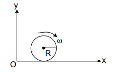
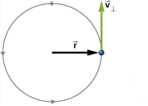
If \(\vec{L}\) and \(\vec{P}\) represent the angular momentum and linear momentum respectively of a particle of mass ‘ \(m\) ‘ having position vector as \(\vec{r}=a(\hat{i} \cos \omega t+\hat{j} \sin \omega t)\). The direction of force is [JEE Main 2025 (Online) 4th April Morning Shift]
CorrectIncorrectHint
(c) The force acting on the particle is directed opposite to the direction of the position vector \(\vec{r}\), which means it is directed towards the origin. It is a centripetal force responsible for the uniform circular motion of the particle.
Derivation
Step 1: Position Vector: The position vector is given by:
\(
\vec{r}=a(\hat{i} \cos \omega t+\hat{j} \sin \omega t)
\)
Step 2: Velocity Vector: Differentiate the position vector with respect to time to find the velocity \(\vec{v}\) :
\(
\vec{v}=\frac{d \vec{r}}{d t}=a(-\hat{i} \omega \sin \omega t+\hat{j} \omega \cos \omega t)=a \omega(-\hat{i} \sin \omega t+\hat{j} \cos \omega t)
\)
Step 3: Acceleration Vector: Differentiate the velocity vector with respect to time to find the acceleration \(\vec{a}\) :
\(
\vec{a}=\frac{d \vec{v}}{d t}=a \omega(-\hat{i} \omega \cos \omega t-\hat{j} \omega \sin \omega t)=-a \omega^2(\hat{i} \cos \omega t+\hat{j} \sin \omega t)
\)
Step 4: Force Vector: According to Newton’s second law, \(\vec{F}=m \vec{a}\).
\(
\begin{aligned}
& \vec{F}=m\left[-a \omega^2(\hat{i} \cos \omega t+\hat{j} \sin \omega t)\right] \\
& \vec{F}=-m \omega^2[a(\hat{i} \cos \omega t+\hat{j} \sin \omega t)] \\
& \vec{F}=-m \omega^2 \vec{r}
\end{aligned}
\)
Since \(m\) and \(\omega^2\) are positive scalars, the force \(\overrightarrow{ F }\) is in the direction opposite to the position vector \(\vec{r}\). This indicates a central force directed towards the origin, which is characteristic of uniform circular motion. - Question 4 of 72
4. Question
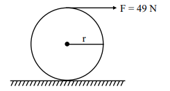
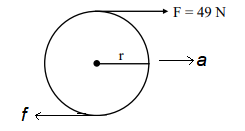
A force of 49 N acts tangentially at the highest point of a sphere (solid) of mass 20 kg , kept on a rough horizontal plane. If the sphere rolls without slipping, then the acceleration of the center of the sphere is [JEE Main 2025 (Online) 3rd April Morning Shift]
 CorrectIncorrect
Hint
(b)
To find the acceleration of the center of the sphere, we must analyze both its translational and rotational motion.
Step 1: Identify the Forces and Constraints
Applied Force \((F)\) : 49 N acting tangentially at the top.
Friction (\(f\)): Acts at the point of contact with the ground.
Mass ( \(m\) ): 20 kg .
Moment of Inertia of a solid sphere \((I): \frac{2}{5} m R^2\).
Rolling Without Slipping Condition: \(a=R \alpha\), where \(a\) is linear acceleration and \(\alpha\) is angular acceleration.
Step 2: Formulate the Equations of Motion
We write the equations for linear and rotational motion about the center of mass:
Translational (Linear):
\(
F+f=m a \dots(1)
\)
(Note: Friction \(f\) acts in the same direction as \(F\) to assist rotation in rolling without slipping when the force is at the top.)
Rotational (Torque): The torque \(\tau\) is produced by both \(F\) and \(f\). Both provide a clockwise torque:
\(
\tau=(F \cdot R)-(f \cdot R)=I \alpha
\)
Divide by \(R\) :
\(
F-f=\frac{I \alpha}{R}
\)
Substitute \(I=\frac{2}{5} m R^2\) and \(\alpha=\frac{a}{R}\) :
\(
F-f=\frac{\left(\frac{2}{5} m R^2\right)\left(\frac{a}{R}\right)}{R}=\frac{2}{5} m a \dots(2)
\)
Step 3: Add Eq. 1 and Eq. 2 to eliminate friction:
\(
\begin{gathered}
(F+f)+(F-f)=m a+\frac{2}{5} m a \\
2 F=\frac{7}{5} m a
\end{gathered}
\)
Rearrange for \(a\) :
\(
a=\frac{10 F}{7 m}
\)
Substitute the given values ( \(F=49 N, m=20 kg\) ):
\(
\begin{gathered}
a=\frac{10 \times 49}{7 \times 20} \\
a=\frac{490}{140}=3.5 m / s^2
\end{gathered}
\)
The acceleration of the center of the sphere is \(3.5 m / s ^2\).Explanation:
Why they are “Subtracted” in the Torque Equation?
When we write the torque equation about the Center of Mass (CM), we look at the “turning effect” of each force:
Torque due to \(F\) : This force is at the top, pushing right. It tries to rotate the sphere clockwise.
\(
\tau_F=F \times R
\)
Torque due to \(f\) : This force is at the bottom, also pushing right. However, because it is below the center of mass, pushing right at the bottom tries to rotate the sphere counterclockwise.
\(
\tau_f=f \times R
\)
Because one force tries to spin the sphere clockwise and the other tries to spin it counterclockwise, their effects oppose each other. In physics, opposite directions are represented by different signs. Thus, the net torque is the difference between them:
\(
\tau_{n e t}=\tau_F-\tau_f=(F-f) R
\)
Summary:
\(
\begin{array}{llll}
\text { Force } & \text { Direction } & \text { Rotation Effect (about CM) } & \text { Sign in Torque Eq } \\
\text { Applied Force }\left(F^{\prime}\right) & \text { Forward } & \text { Clockwise } & \text { Positive }(+) \\
\text { Friction }(f) & \text { Forward } & \text { Counter-clockwise } & \text { Negative }(-)
\end{array}
\) - Question 5 of 72
5. Question
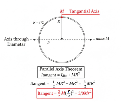
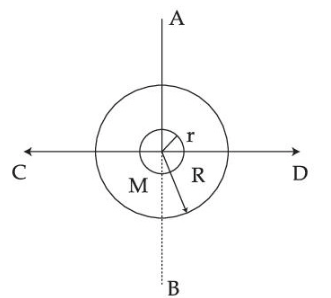
The moment of inertia of a circular ring of mass M and diameter r about a tangential axis lying in the plane of the ring is : [JEE Main 2025 (Online) 2nd April Evening Shift]
CorrectIncorrectHint
(a)

Step 1: Define the Radius
If the diameter is \(r\), then the radius \(R\) is:
\(
R=\frac{r}{2}
\)
Step 2: Moment of Inertia about a Diameter
For a circular ring of mass \(M\) and radius \(R\), the moment of inertia about an axis passing through its diameter (in the plane of the ring) is:
\(
I_{\text {dia }}=\frac{1}{2} M R^2
\)
Step 3: Use the Parallel Axis Theorem
The question asks for the moment of inertia about a tangential axis lying in the plane. This axis is parallel to the diameter and is at a distance equal to the radius ( \(R\) ).
According to the Parallel Axis Theorem:
\(
I_{\text {tangent }}=I_{\text {dia }}+M(\text { distance })^2
\)
\(
\begin{gathered}
I_{\text {tangent }}=\frac{1}{2} M R^2+M R^2 \\
I_{\text {tangent }}=\frac{3}{2} M R^2
\end{gathered}
\)
Step 4: Substitute Diameter ( \(r\) ) back into the equation
Now, we substitute \(R=\frac{r}{2}\) into our result:
\(
\begin{gathered}
I_{\text {tangent }}=\frac{3}{2} M\left(\frac{r}{2}\right)^2 \\
I_{\text {tangent }}=\frac{3}{2} M\left(\frac{r^2}{4}\right) \\
I_{\text {tangent }}=\frac{3}{8} M r^2
\end{gathered}
\) - Question 6 of 72
6. Question
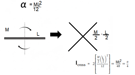
Moment of inertia of a rod of mass ‘ \(M\) ‘ and length ‘ \(L\) ‘ about an axis passing through its center and normal to its length is ‘ \(\alpha\) ‘. Now the rod is cut into two equal parts and these parts are joined symmetrically to form a cross shape. Moment of inertia of cross about an axis passing through its center and normal to plane containing cross is : [JEE Main 2025 (Online) 2nd April Morning Shift]
CorrectIncorrectHint
(a)

To find the moment of inertia of the cross, we need to compare it to the moment of inertia of the original rod.
Step 1: Moment of Inertia of the Original Rod ( \(\alpha\) )
For a rod of mass \(M\) and length \(L\), the moment of inertia about an axis passing through its center and perpendicular to its length is given by:
\(
\alpha=\frac{1}{12} M L^2
\)
Step 2: Properties of the Cut Parts
The rod is cut into two equal parts. For each part:
Mass( \(m\) ): \(\frac{M}{2}\)
Length \((l): \frac{L}{2}\)
Step 3: Moment of Inertia of the Cross
The two parts are joined at their centers to form a cross. The axis passes through this center and is normal to the plane of the cross. This means the axis is perpendicular to both rod segments at their midpoints.
The moment of inertia of one part about its center is:
\(
I_{p a r t}=\frac{1}{12} m l^2
\)
Substitute the values for \(m\) and \(l\) :
\(
\begin{gathered}
I_{p a r t}=\frac{1}{12}\left(\frac{M}{2}\right)\left(\frac{L}{2}\right)^2 \\
I_{p a r t}=\frac{1}{12} \cdot \frac{M}{2} \cdot \frac{L^2}{4}=\frac{1}{96} M L^2
\end{gathered}
\)
Since the cross consists of two such parts rotating about the same axis, the total moment of inertia ( \(I_{\text {cross }}\) ) is:
\(
\begin{gathered}
I_{\text {cross }}=2 \times I_{\text {part }} \\
I_{\text {cross }}=2 \times\left(\frac{1}{96} M L^2\right)=\frac{1}{48} M L^2
\end{gathered}
\)
Step 4: Comparison with \(\alpha\)
Now, we express \(I_{\text {cross }}\) in terms of \(\alpha\) :
\(
\begin{gathered}
I_{\text {cross }}=\frac{1}{48} M L^2=\frac{1}{4}\left(\frac{1}{12} M L^2\right) \\
I_{\text {cross }}=\frac{\alpha}{4}
\end{gathered}
\)
Conclusion: The moment of inertia of the cross is one-fourth of the original rod’s moment of inertia. - Question 7 of 72
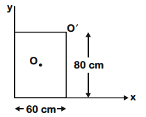
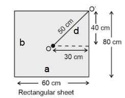
7. Question
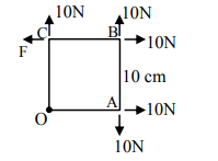
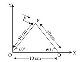
A square Lamina \(0 A B C\) of length 10 cm is pivoted at ‘ \(O ^{\prime}\). Forces act at Lamina as shown in figure. If Lamina remains stationary, then the magnitude of \(F\) is : [JEE Main 2025 (Online) 2nd April Morning Shift]
 CorrectIncorrect
Hint
(a) Step 1: Identify forces and their torques
The problem is solved by applying the principle of moments, which states that for the lamina to remain stationary (in rotational equilibrium) about the pivot point \(O\), the net torque must be zero. The side length of the square is \(L=10 cm\).
We consider torques about point \(O\). Let counterclockwise torques be positive and clockwise torques be negative.
Forces at \(A (10 cm, 0 cm)\) :
10 N force to the right: Acts along the line passing through the pivot \(O\). Perpendicular distance is 0 . Torque \(\tau_{A 1}=0\).
10 N force downwards: Perpendicular distance from \(O\) is 10 cm. Causes clockwise rotation. Torque \(\tau_{A 2}=-(10 N \times 10 cm)=-100 N \cdot cm\).
Forces at \(B (10 cm, 10 cm)\) :
10 N force to the right: Perpendicular distance from \(O\) is 10 cm. Causes counterclockwise rotation. Torque \(\tau_{B 1}=+(10 N \times 10 cm)=+100 N \cdot cm\).
10 N force upwards: Perpendicular distance from \(O\) is 10 cm. Causes counterclockwise rotation. Torque \(\tau_{B 2}=+(10 N \times 10 cm)=+100 N \cdot cm\).
Forces at \(C (0 cm, 10 cm)\) :
10 N force upwards: Acts along the line passing through the pivot \(O\). Perpendicular distance is 0. Torque \(\tau _{ C 1}=0\).
Force \(F\) to the left: Perpendicular distance from \(O\) is \(1 0 ~ c m\). Causes clockwise rotation. Torque \(\tau_{C 2}=-(F \times 10 cm)\).
Step 2: Sum the torques and solve for \(F\)
For the lamina to be stationary, the net torque must be zero:
\(
\sum \tau=\tau_{A 1}+\tau_{A 2}+\tau_{B 1}+\tau_{B 2}+\tau_{C 1}+\tau_{C 2}=0
\)
\(
\begin{gathered}
0-100 N \cdot cm+100 N \cdot cm+100 N \cdot cm+0-(F \times 10 cm)=0 \\
100 N \cdot cm-(F \times 10 cm)=0 \\
F \times 10 cm=100 N \cdot cm \\
F=\frac{100 N \cdot cm}{10 cm} \\
F=10 N
\end{gathered}
\) - Question 8 of 72
8. Question
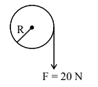
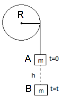
A cord of negligible mass is wound around the rim of a wheel supported by spokes with negligible mass. The mass of wheel is 10 kg and radius is 10 cm and it can freely rotate without any friction. Initially the wheel is at rest. If a steady pull of 20 N is applied on the cord, the angular velocity of the wheel, after the cord is unwound by 1 m, would be: [JEE Main 2025 (Online) 2nd April Morning Shift]
 CorrectIncorrect
Hint
(a) To find the angular velocity of the wheel, we can use the Work-Energy Theorem for rotational motion. This approach is often faster than calculating torque and acceleration separately.
Step 1: Identify the Given Data
Mass of the wheel (\(M\)): 10 kg
Radius of the wheel ( \(R\) ): \(10 cm=0.1 m\)
Steady Pull/Force ( \(F\) ): 20 N
Length of cord unwound (\(d\)): 1 m
Initial angular velocity \(\left(\omega_i\right): 0 rad / s\) (at rest)
Step 2: Work Done by the Pulling Force
The work done ( \(W\) ) by the force on the cord is converted into the rotational kinetic energy of the wheel. Since the force is steady and acts along the displacement of the cord:
\(
\begin{gathered}
W=F \times d \\
W=20 N \times 1 m=20 J
\end{gathered}
\)
Step 3: Moment of Inertia (\(I\))
A wheel with its mass concentrated at the rim (supported by negligible spokes) acts like a circular ring. The moment of inertia for a ring about its central axis is:
\(
\begin{gathered}
I=M R^2 \\
I=10 kg \times(0.1 m)^2=10 \times 0.01=0.1 kg \cdot m^2
\end{gathered}
\)
Step 4: Rotational Kinetic Energy ( \(K_{\text {rot }}\) )
According to the Work-Energy Theorem:
\(
W=\Delta K_{r o t}=\frac{1}{2} I \omega^2-\frac{1}{2} I \omega_i^2
\)
Since \(\omega_i=0\) :
\(
20=\frac{1}{2}(0.1) \omega^2
\)
\(
\omega=20 rad / s
\)
The angular velocity of the wheel after 1 m of cord is unwound is \(20 rad / s\). - Question 9 of 72
9. Question
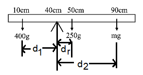
A uniform rod of mass 250 g having length 100 cm is balanced on a sharp edge at 40 cm mark. A mass of 400 g is suspended at 10 cm mark. To maintain the balance of the rod, the mass to be suspended at 90 cm mark, is [JEE Main 2025 (Online) 28th January Evening Shift]
CorrectIncorrectHint
(c)

To solve this, we apply the principle of Rotational Equilibrium. For the rod to be balanced, the net torque about the pivot point (the sharp edge) must be zero.
Step 1: Identify the Forces and their Positions
Pivot Point: 40 cm mark.
Rod’s Weight ( \(W_{\text {rod }}\) ): Since the rod is uniform, its weight acts at its center of mass ( 50 cm mark).
Mass of rod \(\left(m_r\right)=250 g\)
Distance from pivot \(\left(d_r\right)=50-40=10 cm\) (to the right of the pivot)
Suspended Mass \(1\left(m_1\right)\) :
Mass \(\left(m_1\right)=400 g\)
Position = 10 cm mark.
Distance from pivot \(\left(d_1\right)=40-10=30 cm\) (to the left of the pivot)
Suspended Mass \(2\left(m_2\right)\) :
Mass \(\left(m_2\right)=\) Unknown (to be found)
Position \(=90 cm\) mark.
Distance from pivot \(\left(d_2\right)=90-40=50 cm\) (to the right of the pivot)
Step 2: Set Up the Torque Equation
Torque ( \(\tau\) ) is given by \(m \times g \times d\). Since \(g\) is common to all terms, we can simplify the equilibrium condition ( \(\sum \tau=0\) ) to:
Sum of Clockwise Moments = Sum of Counter-Clockwise Moments
Counter-Clockwise (left of pivot): Produced by \(m_1\).
\(
\tau_{C C W}=400 \times 30
\)
Clockwise (right of pivot): Produced by the rod’s own weight and \(m_2\).
\(
\tau_{C W}=(250 \times 10)+\left(m_2 \times 50\right)
\)
Step 3: Calculate the Unknown Mass ( \(m_2\) )
Equating the moments:
\(
\begin{gathered}
400 \times 30=(250 \times 10)+\left(m_2 \times 50\right) \\
12000=2500+50 m_2
\end{gathered}
\)
\(
m_2=190 g
\)
To maintain the balance of the rod, the mass to be suspended at the 90 cm mark is 190 g. - Question 10 of 72
10. Question
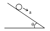
A solid sphere and a hollow sphere of the same mass and of same radius are rolled on an inclined plane. Let the time taken to reach the bottom by the solid sphere and the hollow sphere be \(t_1\) and \(t_2\), respectively, then [JEE Main 2025 (Online) 24th January Evening Shift]
CorrectIncorrectHint
(a)

To compare the time taken by a solid sphere and a hollow sphere to roll down an inclined plane, we need to look at their acceleration.
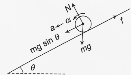
Step 1: Acceleration Formula for Rolling
For any object of mass \(M\), radius \(R\), and moment of inertia \(I\) rolling down an incline of angle \(\theta\), the acceleration ( \(a\) ) is given by:
\(
a=\frac{g \sin \theta}{1+\frac{I}{M R^2}}
\)
Since both spheres start from rest and travel the same distance ( \(s\) ), the time taken ( \(t\) ) is inversely proportional to the square root of acceleration:
\(
s=\frac{1}{2} a t^2 \Longrightarrow t=\sqrt{\frac{2 s}{a}}
\)
Therefore, the object with the higher acceleration will take less time.
Step 2: Compare Moments of Inertia ( \(I\) )
Solid Sphere \(\left(I_1\right): \frac{2}{5} M R^2=0.4 M R^2\)
Hollow Sphere \(\left(I_2\right): \frac{2}{3} M R^2 \approx 0.67 M R^2\)
Step 3: Compare Accelerations
Let’s plug the values into the acceleration formula:
Acceleration of Solid Sphere ( \(a_1\) ):
\(
a_1=\frac{g \sin \theta}{1+0.4}=\frac{g \sin \theta}{1.4}
\)
Acceleration of Hollow Sphere ( \(a_2\) ):
\(
a_2=\frac{g \sin \theta}{1+0.67}=\frac{g \sin \theta}{1.67}
\)
Since \(1.4<1.67\), it follows that \(a_1>a_2\). The solid sphere has a higher acceleration because more of its mass is concentrated toward the center, making it easier to rotate (lower rotational inertia).
Step 4: Conclusion on Time
Because the solid sphere accelerates faster ( \(a_1>a_2\) ), it will reach the bottom in less time.
\(t_1<t_2\)
Correct Answer: \(t_1<t_2\) (The solid sphere reaches first). - Question 11 of 72
11. Question
A solid sphere is rolling without slipping on a horizontal plane. The ratio of the linear kinetic energy of the centre of mass of the sphere and rotational kinetic energy is : [JEE Main 2025 (Online) 24th January Evening Shift]
CorrectIncorrectHint
(c) To find the ratio of linear (translational) kinetic energy to rotational kinetic energy for a solid sphere rolling without slipping, we analyze the two components of its total kinetic energy.
Step 1: Translational Kinetic Energy ( \(K_{\text {trans }}\) )
The linear kinetic energy of the center of mass is given by:
\(
K_{\text {trans }}=\frac{1}{2} M v^2
\)
where \(M\) is the mass of the sphere and \(v\) is its linear velocity.
STep 2: Rotational Kinetic Energy ( \(K_{\text {rot }}\) )
The rotational kinetic energy is given by:
\(
K_{r o t}=\frac{1}{2} I \omega^2
\)
For a solid sphere, the moment of inertia (I) about its center is:
\(
I=\frac{2}{5} M R^2
\)
The condition for rolling without slipping is \(v=R \omega\), or \(\omega=\frac{v}{R}\). Substituting these into the formula for \(K_{\text {rot }}\) :
\(
\begin{gathered}
K_{r o t}=\frac{1}{2}\left(\frac{2}{5} M R^2\right)\left(\frac{v}{R}\right)^2 \\
K_{r o t}=\frac{1}{5} M v^2
\end{gathered}
\)
Step 3: Calculating the Ratio
Now, we find the ratio of the linear kinetic energy to the rotational kinetic energy:
\(
\begin{gathered}
\text { Ratio }=\frac{K_{\text {trans }}}{K_{\text {rot }}}=\frac{\frac{1}{2} M v^2}{\frac{1}{5} M v^2} \\
\text { Ratio }=\frac{1 / 2}{1 / 5}=\frac{5}{2}
\end{gathered}
\)
Conclusion: The ratio of the linear kinetic energy of the center of mass to the rotational kinetic energy is 5:2. - Question 12 of 72
12. Question
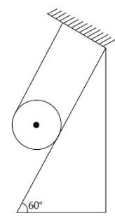
A uniform solid cylinder of mass ‘ \(m\) ‘ and radius ‘ \(r\) ‘ rolls along an inclined rough plane of inclination \(45^{\circ}\). If it starts to roll from rest from the top of the plane then the linear acceleration of the cylinder’s axis will be [JEE Main 2025 (Online) 24th January Morning Shift]
CorrectIncorrectHint
(d) To find the linear acceleration of a uniform solid cylinder rolling without slipping down an inclined plane, we apply the principles of rotational and translational dynamics.Step 1: General Formula for Acceleration
For any object of mass \(m\), radius \(r\), and moment of inertia \(I\) rolling down an incline of angle \(\theta\), the linear acceleration ( \(a\) ) is:
\(
a=\frac{g \sin \theta}{1+\frac{I}{m r^2}}
\)
Step 2: Properties of a Solid Cylinder
For a solid cylinder, the moment of inertia about its central axis is:
\(
I=\frac{1}{2} m r^2
\)
Substituting this into the term \(\frac{I}{m r^2}\) gives us:
\(
\frac{I}{m r^2}=\frac{1}{2}
\)
Step 3: Calculation for \(4 5 { }^{ \circ }\)
Given:
\(\theta=45^{\circ}\)
\(\sin 45^{\circ}=\frac{1}{\sqrt{2}}\)
Now, substitute these values into the acceleration formula:
\(
a=\frac{g\left(\frac{1}{\sqrt{2}}\right)}{1+\frac{1}{2}}
\)
Simplify the denominator:
\(
a=\frac{\frac{g}{\sqrt{2}}}{\frac{3}{2}}
\)
Rearrange the fraction:
\(
a=\frac{g}{\sqrt{2}} \cdot \frac{2}{3}
\)
\(
a=\frac{\sqrt{2} g}{3}
\)
The linear acceleration of the cylinder’s axis is \(\frac{\sqrt{2} g}{3}\).
Alternate: Step 1: Forces Acting on the Cylinder
For a rolling object on an inclined plane, the forces acting are:
Gravitational force ( \(m g\) ):
Component along the incline: \(m g \sin \theta\)
Component perpendicular to the incline: \(m g \cos \theta\)
Normal reaction force ( \(N\) ): Acts perpendicular to the inclined surface.
Friction force ( \(f\) ): Provides the necessary torque for rolling motion (without slipping). It acts up the incline.
Step 2: Equations of Motion
1. Translational Motion
From Newton’s Second Law along the incline:
\(
m g \sin \theta-f=m a
\)
where \(a\) is the linear acceleration of the cylinder.
2. Rotational Motion
For rotation about the center, using Torque Equation:
\(
f r=I \alpha
\)
For a solid cylinder, the moment of inertia about its axis is:
\(
I=\frac{1}{2} m r^2
\)
Using the pure rolling condition: \(\alpha=\frac{a}{r^{\prime}}\),
\(
\begin{gathered}
f r=\left(\frac{1}{2} m r^2\right) \frac{a}{r} \\
f=\frac{1}{2} m a
\end{gathered}
\)
Step 3: Solve for Acceleration
Substituting \(f=\frac{1}{2} m a\) into the translational equation:
\(
m g \sin \theta-\frac{1}{2} m a=m a
\)
\(
\begin{aligned}
&a=\frac{2}{3} g \sin \theta\\
&\text { Substituting } \theta=45^{\circ} \text {, we get: }\\
&\begin{gathered}
a=\frac{2}{3} g \sin 45^{\circ} \\
a=\frac{2}{3} g \times \frac{1}{\sqrt{2}} \\
a=\frac{2 g}{3 \sqrt{2}} \\
a=\frac{\sqrt{2} g}{3}
\end{gathered}
\end{aligned}
\) - Question 13 of 72
13. Question
A circular disk of radius R meter and mass M kg is rotating around the axis perpendicular to the disk. An external torque is applied to the disk such that \(\theta(t)=5 t^2-8 t\), where \(\theta(t)\) is the angular position of the rotating disc as a function of time \(t\). How much power is delivered by the applied torque, when \(t=2 s\) ? [JEE Main 2025 (Online) 23rd January Evening Shift]
CorrectIncorrectHint
(a) To find the power delivered by the applied torque at a specific time, we can use the relationship between power, torque, and angular velocity.
Step 1: Identify the Relevant Formulas
The power \(P\) delivered by a torque \(\tau\) to a rotating object is given by:
\(
P=\tau \omega
\)
Where:
\(\omega\) is the angular velocity: \(\omega=\frac{d \theta}{d t}\)
\(\tau\) is the torque: \(\tau=I \alpha\)
\(I\) is the moment of inertia of the disk: \(I=\frac{1}{2} M R^2\)
\(\alpha\) is the angular acceleration: \(\alpha=\frac{d \omega}{d t}\)
Step 2: Differentiate the Angular Position
Given the angular position function \(\theta(t)=5 t^2-8 t\) :
Angular Velocity ( \(\omega\) ):
\(
\omega(t)=\frac{d}{d t}\left(5 t^2-8 t\right)=10 t-8
\)
Angular Acceleration ( \(\alpha\) ):
\(
\alpha(t)=\frac{d}{d t}(10 t-8)=10 rad / s^2
\)
Step 3: Calculate Values at \(t=2 s\)
Now, we substitute \(t=2\) into our equations:
Angular Velocity at 2s:
\(
\omega(2)=10(2)-8=12 rad / s
\)
Torque ( \(\tau\) ): Using \(I=\frac{1}{2} M R^2\) and \(\alpha=10\) :
\(
\tau=\left(\frac{1}{2} M R^2\right)(10)=5 M R^2 N \cdot m
\)
Step 4: Calculate the Power
Finally, multiply the torque by the angular velocity at \(t=2 s\) :
\(
\begin{gathered}
P=\tau \cdot \omega(2) \\
P=\left(5 M R^2\right) \cdot(12) \\
P=60 M R^2 \text { Watts }
\end{gathered}
\)
Final Answer: The power delivered by the applied torque at \(t=2 s\) is \(60 M R^2\) Watts. - Question 14 of 72
14. Question
A solid sphere of mass ‘ \(m\) ‘ and radius ‘ \(r\) ‘ is allowed to roll without slipping from the highest point of an inclined plane of length ‘ \(L^{\prime}\) and makes an angle \(30^{\circ}\) with the horizontal. The speed of the particle at the bottom of the plane is \(v_1\). If the angle of inclination is increased to \(45^{\circ}\) while keeping \(L\) constant. Then the new speed of the sphere at the bottom of the plane is \(v_2\). The ratio \(v_1^2: v_2^2\) is [JEE Main 2025 (Online) 23rd January Morning Shift]
CorrectIncorrectHint
(c)

To find the ratio \(v_1^2: v_2^2\) for a solid sphere rolling without slipping down an inclined plane, we use the principle of conservation of mechanical energy.
Case-1: Physics Principles
For a round object (like a solid sphere) rolling down an inclined plane of height \(h\) from rest, the potential energy at the top is converted into both translational and rotational kinetic energy at the bottom:
\(
m g h=\frac{1}{2} m v^2+\frac{1}{2} I \omega^2
\)
For a solid sphere, the moment of inertia about its center is \(I=\frac{2}{5} m r^2\). Since it rolls without slipping, we have the condition \(v=\omega r\), or \(\omega=\frac{v}{r}\).
Substituting these into the energy equation:
\(
\begin{gathered}
m g h=\frac{1}{2} m v^2+\frac{1}{2}\left(\frac{2}{5} m r^2\right)\left(\frac{v}{r}\right)^2 \\
m g h=\frac{1}{2} m v^2+\frac{1}{5} m v^2 \\
m g h=\frac{7}{10} m v^2
\end{gathered}
\)
\(
v^2=\frac{10}{7} g h
\)
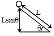
Case-2: Relate Height to Incline Length
The vertical height \(h\) of an inclined plane of slant length \(L\) and angle of inclination \(\theta\) is:
\(
h=L \sin \theta
\)
Substituting this into the expression for \(v^2\) :
\(
v^2=\frac{10}{7} g L \sin \theta
\)
Since the mass \(m\), radius \(r\), gravity \(g\), and length \(L\) are constant in both cases, \(v^2\) is directly proportional to \(\sin \theta\) :
\(
v^2 \propto \sin \theta
\)
Case-3: Calculate the Ratio
We are given two cases with different angles of inclination:
Case 1: \(\theta_1=30^{\circ}\), speed is \(v_1\)
Case 2: \(\theta_2=45^{\circ}\), speed is \(v_2\)
The ratio \(v_1^2: v_2^2\) is:
\(
\frac{v_1^2}{v_2^2}=\frac{\sin 30^{\circ}}{\sin 45^{\circ}}
\)
Substituting the values \(\sin 30^{\circ}=\frac{1}{2}\) and \(\sin 45^{\circ}=\frac{1}{\sqrt{2}}\) :
\(
\begin{gathered}
\frac{v_1^2}{v_2^2}=\frac{1 / 2}{1 / \sqrt{2}} \\
\frac{v_1^2}{v_2^2}=\frac{1}{2} \times \sqrt{2}=\frac{\sqrt{2}}{2} \\
\frac{v_1^2}{v_2^2}=\frac{1}{\sqrt{2}}
\end{gathered}
\)
Thus, the ratio \(v_1^2: v_2^2\) is \(1: \sqrt{2}\). - Question 15 of 72
15. Question
The torque due to the force \((2 \hat{i}+\hat{j}+2 \hat{k})\) about the origin, acting on a particle whose position vector is \((\hat{i}+\hat{j}+\hat{k})\), would be [JEE Main 2025 (Online) 22nd January Evening Shift]
CorrectIncorrectHint
(b) First, torque \((\vec{\tau})\) is found by taking the cross product of the position vector \((\vec{r})\) and the force vector \((\vec{F})\) :
\(
\vec{\tau}=\vec{r} \times \vec{F}
\)
Here, \(\vec{r}=\hat{i}+\hat{j}+\hat{k}\) and \(\vec{F}=2 \hat{i}+\hat{j}+2 \hat{k}\).
We use a determinant to find the cross product: \(\vec{\tau}=\left|\begin{array}{lll}\hat{i} & \hat{j} & \hat{k} \\ 1 & 1 & 1 \\ 2 & 1 & 2\end{array}\right|\)
Expanding the determinant:
\(
\vec{\tau}=\hat{i}[(1)(2)-(1)(1)]-\hat{j}[(1)(2)-(1)(2)]+\hat{k}[(1)(1)-(1)(2)]
\)
This gives: \(\vec{\tau}=\hat{i}(2-1)-\hat{j}(2-2)+\hat{k}(1-2)\)
So, \(\vec{\tau}=\hat{i}-0 \hat{j}-\hat{k}=\hat{i}-\hat{k}\) - Question 16 of 72
16. Question
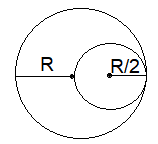
A uniform circular disc of radius \(R\) and mass \(M\) is rotating about an axis perpendicular to its plane and passing through its centre. A small circular part of radius \(R / 2\) is removed from the original disc as shown in the figure. Find the moment of inertia of the remaining part of the original disc about the axis as given above. [JEE Main 2025 (Online) 22nd January Morning Shift]
 CorrectIncorrect
Hint
(b) To find the moment of inertia of the remaining part of the disc, we use the principle of superposition. This states that the moment of inertia of the final object is the moment of inertia of the original object minus the moment of inertia of the removed part (about the same axis).
STep 1: Moment of Inertia of the Original Disc
For a uniform circular disc of mass \(M\) and radius \(R\), the moment of inertia about its central axis (perpendicular to the plane) is:
\(
I_{\text {original }}=\frac{1}{2} M R^2
\)
Step 2: Properties of the Removed Disc
The removed part is a smaller disc of radius \(r=\frac{R}{2}\). Assuming uniform thickness and density, its mass \((m)\) is proportional to its area:
Area of original disc: \(A_1=\pi R^2\)
Area of removed disc: \(A_2=\pi\left(\frac{R}{2}\right)^2=\frac{\pi R^2}{4}\)
Since Area is \(\frac{1}{4}\) of the original, the mass of the removed part is \(m=\frac{M}{4}\).
Step 3: Moment of Inertia of the Removed part.
The removed disc is not centered on the original axis. As shown in figure, usually depicts the small disc’s edge touching the center of the large disc, meaning its center is at a distance \(d=\frac{R}{2}\) from the original center.
We calculate its moment of inertia about the original axis using the Parallel Axis Theorem:
\(
\begin{gathered}
I_{\text {removed }}=I_{cm}+m d^2 \\
I_{\text {removed }}=\left[\frac{1}{2} m\left(\frac{R}{2}\right)^2\right]+m\left(\frac{R}{2}\right)^2 \\
I_{\text {removed }}=\frac{1}{2}\left(\frac{M}{4}\right) \frac{R^2}{4}+\left(\frac{M}{4}\right) \frac{R^2}{4} \\
I_{\text {removed }}=\frac{M R^2}{32}+\frac{M R^2}{16}=\frac{M R^2+2 M R^2}{32}=\frac{3}{32} M R^2
\end{gathered}
\)
Step 4: Moment of Inertia of the Remaining Part
Finally, subtract the removed part’s inertia from the original:
\(
\begin{gathered}
I_{\text {remaining }}=I_{\text {original }}-I_{\text {removed }} \\
I_{\text {remaining }}=\frac{1}{2} M R^2-\frac{3}{32} M R^2 \\
I_{\text {remaining }}=\frac{16}{32} M R^2-\frac{3}{32} M R^2 \\
I_{\text {remaining }}=\frac{13}{32} M R^2
\end{gathered}
\)
Final Answer: The moment of inertia of the remaining part is \(\frac{13}{32} M R^2\). - Question 17 of 72
17. Question
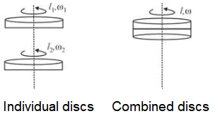
A thin circular disc of mass M and radius R is rotating in a horizontal plane about an axis passing through its centre and perpendicular to its plane with angular velocity \(\omega\). If another disc of same dimensions but of mass \(M / 2\) is placed gently on the first disc co-axially, then the new angular velocity of the system is : [JEE Main 2024 (Online) 8th April Evening Shift]
CorrectIncorrectHint
(d) This problem can be solved using the Principle of Conservation of Angular Momentum, because there is no external torque acting on the system. When the second disc is placed gently on the first, the internal friction between them eventually causes both to rotate together at a new common angular velocity.
Step 1: Conservation of Angular Momentum
The law states that if the net external torque is zero, the initial angular momentum ( \(L_i\) ) must equal the final angular momentum ( \(L_f\) ):
\(
\begin{gathered}
L_i=L_f \\
I_1 \omega_1=\left(I_1+I_2\right) \omega_2
\end{gathered}
\)
Step 2: Identify Moments of Inertia
Disc 1 (Original):
Mass \(=M\), Radius \(=R\)
\(I_1=\frac{1}{2} M R^2\)
Initial angular velocity \(= \omega\)
Disc 2 (Added):
Mass \(=M / 2\), Radius \(=R\)
\(I_2=\frac{1}{2}\left(\frac{M}{2}\right) R^2=\frac{1}{4} M R^2\)
Step 3: Calculate Final Angular Velocity ( \(\omega_2\) )
Substitute the values into the conservation equation:
\(
\left(\frac{1}{2} M R^2\right) \omega=\left(\frac{1}{2} M R^2+\frac{1}{4} M R^2\right) \omega_2
\)
Simplify the moment of inertia on the right side:
\(
\frac{1}{2} M R^2+\frac{1}{4} M R^2=\frac{2}{4} M R^2+\frac{1}{4} M R^2=\frac{3}{4} M R^2
\)
Now, solve for \(\omega_2\) :
\(
\left(\frac{1}{2} M R^2\right) \omega=\left(\frac{3}{4} M R^2\right) \omega_2
\)
\(
\omega_2=\frac{2}{3} \omega
\)
The new angular velocity of the system is \(\frac{2}{3} \omega\). - Question 18 of 72
18. Question
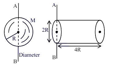
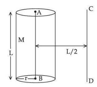
Ratio of radius of gyration of a hollow sphere to that of a solid cylinder of equal mass, for moment of Inertia about their diameter axis \(A B\) as shown in figure is \(\sqrt{8 / x}\). The value of \(x\) is : [JEE Main 2024 (Online) 5th April Morning Shift]
 CorrectIncorrect
Hint
(c) To find the value of \(x\), we need to calculate the radii of gyration for both the hollow sphere and the solid cylinder about the specific axis \(A B\) shown in the image.
STep 1: Moment of Inertia of the Hollow Sphere ( \(I_H\) )
For a hollow sphere of mass \(M\) and radius \(R\), the moment of inertia about its diameter (axis \(A B)\) is:
\(
I_H=\frac{2}{3} M R^2
\)
The radius of gyration \(k_1\) is defined by \(I_H=M k_1^2\) :
\(
k_1=\sqrt{\frac{2}{3}} R \Longrightarrow k_1^2=\frac{2}{3} R^2
\)
Step 2: Moment of Inertia of the Solid Cylinder ( \(I_C\) )
The axis \(A B\) for the cylinder is a diameter at one end. For a cylinder of mass \(M\), radius \(R\), and length \(L\), the moment of inertia about a diameter passing through its center is \(M\left(\frac{R^2}{4}+\right. \left.\frac{L^2}{12}\right)\).
Using the Parallel Axis Theorem, the moment of inertia about the end diameter \((A B)\) is:
\(
\begin{gathered}
I_C=I_{\text {center }}+M\left(\frac{L}{2}\right)^2 \\
I_C=M\left(\frac{R^2}{4}+\frac{L^2}{12}\right)+M\left(\frac{L^2}{4}\right)=M\left(\frac{R^2}{4}+\frac{L^2}{3}\right)
\end{gathered}
\)
From the figure, the length of the cylinder is \(L=4 R\). Substituting this:
\(
\begin{gathered}
I_C=M\left(\frac{R^2}{4}+\frac{(4 R)^2}{3}\right)=M\left(\frac{R^2}{4}+\frac{16 R^2}{3}\right) \\
I_C=M\left(\frac{3 R^2+64 R^2}{12}\right)=\frac{67}{12} M R^2
\end{gathered}
\)
The radius of gyration \(k_2\) for the cylinder is:
\(
k_2^2=\frac{67}{12} R^2
\)
Step 3: Calculate the Ratio and Find \(x\)
The ratio of their radii of gyration is given as:
\(
\frac{k_1}{k_2}=\sqrt{\frac{k_1^2}{k_2^2}}=\sqrt{\frac{\frac{2}{3} R^2}{\frac{67}{12} R^2}}=\sqrt{\frac{2}{3} \times \frac{12}{67}}=\sqrt{\frac{8}{67}}
\)
Comparing this with the given ratio \(\sqrt{8 / x}\) :
\(
\sqrt{\frac{8}{67}}=\sqrt{\frac{8}{x}}
\)
Final Answer: The value of \(x\) is \(6 7.\) - Question 19 of 72
19. Question
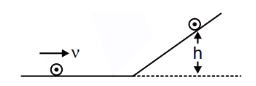
A disc of radius R and mass M is rolling horizontally without slipping with speed \(v\). It then moves up an inclined smooth surface as shown in figure. The maximum height that the disc can go up the incline is : [JEE Main 2024 (Online) 1st February Evening Shift]
 CorrectIncorrect
Hint
(b) In physics problems involving rolling motion, the term “smooth” is the most critical descriptor because it dictates whether rotational energy can be converted into potential energy.
Step 1: Initial Energy (Rolling Without Slipping)
On the horizontal floor, the disc has both translational and rotational kinetic energy.
Translational Kinetic Energy \(\left(K_T\right): \frac{1}{2} M v^2\)
Rotational Kinetic Energy \(\left(K_R\right): \frac{1}{2} I \omega^2=\frac{1}{2}\left(\frac{1}{2} M R^2\right)\left(\frac{v}{R}\right)^2=\frac{1}{4} M v^2\)
Total Energy \(\left(E_i\right): \frac{3}{4} M v^2\)
Step 2: Behavior on a Smooth Incline
The transition to a smooth surface changes the dynamics of the rotation:
No Friction = No Torque: A smooth surface cannot exert a frictional force parallel to the incline. Without friction, there is no torque acting on the disc about its center of mass.
Conservation of Angular Velocity: Because the net torque is zero, the angular acceleration \(\alpha\) is zero. Consequently, the angular velocity \(\omega\) remains constant throughout the climb.
Energy “Trapping”: Since \(\omega\) does not change, the rotational kinetic energy ( \(\frac{1}{4} M v^2\) ) remains constant. It is not converted into potential energy; the disc simply keeps spinning at the same rate even as it stops moving upward.
Step 3: Conservation of Energy Calculation
At the maximum height \(h\), the translational velocity is zero, but the rotational energy remains at its initial value.
\(
\begin{gathered}
E_{\text {initial }}=E_{\text {final }} \\
\left(K_{\text {translational }}+K_{\text {rotational }}\right)_{\text {initial }}=\left(\text { Potential Energy }+K_{\text {rotational }}\right)_{\text {final }} \\
\frac{1}{2} M v^2+\frac{1}{4} M v^2=M g h+\frac{1}{4} M v^2
\end{gathered}
\)
The rotational energy terms cancel out from both sides, leaving only the translational energy to be converted:
\(
\begin{gathered}
\frac{1}{2} M v^2=M g h \\
h=\frac{v^2}{2 g}
\end{gathered}
\)
Final Answer: For a smooth inclined surface, the maximum height is \(\frac{v^2}{2 g}\). - Question 20 of 72
20. Question
A particle of mass m is projected with a velocity ‘ \(u\) ‘ making an angle of \(30^{\circ}\) with the horizontal. The magnitude of angular momentum of the projectile about the point of projection when the particle is at its maximum height \(h\) is : [JEE Main 2024 (Online) 30th January Morning Shift]
CorrectIncorrectHint
(d) To find the angular momentum of the projectile about the point of projection at its maximum height, we use the definition of angular momentum for a point mass.
Step 1: Physics Principles
The angular momentum ( \(L\) ) of a particle relative to a point is given by the cross product of its position vector \((r)\) and its linear momentum \((p)\) :
\(
L=r \times p=r \times(m v)
\)
In magnitude terms, this is simplified to:
\(
L=L=m v r_{\perp}
\)
Where \(r_{\perp}\) is the perpendicular distance from the point of projection to the line of motion of the particle.
Step 2: Identify the Variables at Maximum Height
For a particle projected with velocity \(u\) at an angle \(\theta=30^{\circ}\) :
Velocity at max height ( \(v\) ): At the highest point, the vertical component of velocity is zero. Only the horizontal component remains:
\(
v_x=u \cos 30^{\circ}=u \frac{\sqrt{3}}{2}
\)
Position at max height: The particle is at a vertical height \(h\) from the horizontal axis. The line of motion at this instant is horizontal.
Perpendicular distance \(\left(r_{\perp}\right)\) : The perpendicular distance from the origin (point of projection) to the horizontal line of motion at the peak is simply the maximum height \(h\).
\(
h=\frac{u^2 \sin ^2 \theta}{2 g}=\frac{u^2 \sin ^2 30^{\circ}}{2 g}
\)
Since \(\sin 30^{\circ}=1 / 2\), then \(\sin ^2 30^{\circ}=1 / 4\) :
\(
h=\frac{u^2(1 / 4)}{2 g}=\frac{u^2}{8 g}
\)
Step 3: Calculate Angular Momentum ( \(L\) )
Using the formula \(L=m \cdot v_x \cdot h\) :
\(
L=m\left(u \frac{\sqrt{3}}{2}\right)\left(\frac{u^2}{8 g}\right)
\)
Multiply the terms together:
\(
L=\frac{\sqrt{3} m u^3}{16 g}
\)
The magnitude of the angular momentum is \(\frac{\sqrt{3}}{16} \frac{m u^3}{g}\). - Question 21 of 72
21. Question
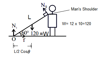
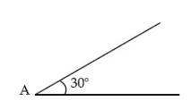
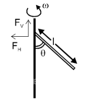
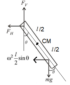
A heavy iron bar of weight 12 kg is having its one end on the ground and the other on the shoulder of a man. The rod makes an angle \(60^{\circ}\) with the horizontal, the weight experienced by the man is : [JEE Main 2024 (Online) 27th January Evening Shift]
CorrectIncorrectHint
(b)

Step 1:
From the diagram, the iron bar has a length \(L\) and is in equilibrium with the following forces acting on it:
Weight ( \(W\) ): Given as 12 kg , which corresponds to a force of \(12 \times 10=120 N\) acting vertically downwards at the center of mass ( \(L / 2\) ).
Pivot Point \((O)\) : The end of the rod touching the ground.
Shoulder Force \(\left(N_s\right)\) : The normal force the man’s shoulder exerts perpendicular to the rod at its far end \((L)\).
Angle ( \(\theta\) ): The rod is inclined at \(60^{\circ}\) to the horizontal.
Step 2: Rotational Equilibrium (Torque Balance)
To find the force \(N_s\) that the man experiences, we calculate the net torque about the pivot point \(O\) at the ground. This eliminates the unknown reaction forces at the ground ( \(N_l\) and friction \(f\) ) from our equation.
For equilibrium, the clockwise torque must equal the counter-clockwise torque:
\(
\sum \tau_O=0
\)
Torque due to Weight: The vertical force \(W\) acts at a horizontal distance of \(\frac{L}{2} \cos 60^{\circ}\) from the pivot.
Torque due to Shoulder Force: Since the diagram shows \(N_s\) is perpendicular to the rod, its lever arm is the full length of the rod, \(L\).
\(
W \cdot\left(\frac{L}{2} \cos 60^{\circ}\right)=N_s \cdot L
\)
Step 3: Step-by-Step Calculation:
Substitute the known values ( \(W=120 N\) and \(\cos 60^{\circ}=0.5\) ) into the equation:
(i) Cancel \(L\) from both sides:
\(
W \cdot\left(\frac{1}{2} \cdot 0.5\right)=N_s
\)
(ii) Plug in the weight:
\(
120 \cdot 0.25=N_s
\)
(iii) Calculate the force in Newtons:
\(
N_s=30 N
\)
Step 4: Convert the force back to a mass equivalent (as “weight experienced” in kg ):
\(
\text { Weight experienced }=\frac{30 N}{10 m / s^2}=3 kg
\)
Final Answer: The weight experienced by the man is 3 kg. - Question 22 of 72
22. Question
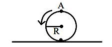
A disc is rolling without slipping on a surface. The radius of the disc is \(R\). At \(t=0\), the top most point on the disc is A as shown in figure. When the disc completes half of its rotation, the displacement of point A from its initial position is [JEE Main 2023 (Online) 13th April Morning Shift]
 CorrectIncorrect
Hint
(c)

\(
\begin{aligned}
\text { Displacement } & =\sqrt{(2 R)^2+(\pi R)^2} \\
& =R \sqrt{4+\pi^2}
\end{aligned}
\)Explanation: To find the displacement of point \(A\) after half a rotation, we need to determine its initial and final coordinates in a Cartesian plane.
Step 1: Initial Position of Point A ( \(t=0\) )
Let the point of contact between the disc and the surface at \(t=0\) be the origin \((0,0)\). Since the disc has a radius \(R\) and point \(A\) is at the very top, its initial coordinates are:
\(
\left(x_1, y_1\right)=(0,2 R)
\)
Step 2: Final Position of Point A (After half rotation)
When the disc completes half of its rotation \((\theta=\pi)\) :
Horizontal Distance Moved by Center: Since the disc rolls without slipping, the center of mass moves a distance equal to the arc length of the rotation. For a half rotation, this distance is \(\pi R\).
Position of A Relative to Center: After half a rotation, the point that was at the top ( \(A\) ) rotates \(180^{\circ}\) and is now at the very bottom (the point of contact with the ground).
Coordinates of A:
Horizontal position ( \(x_2\) ): The center moved \(\pi R\), and since \(A\) is now directly below the center, \(x_2=\pi R\).
Vertical position ( \(y_2\) ): Since \(A\) is at the point of contact on the ground, \(y_2=0\).
\(
\left(x_2, y_2\right)=(\pi R, 0)
\)
Displacement is the straight-line distance between the initial and final positions. We use the distance formula:
\(
d=\sqrt{\left(x_2-x_1\right)^2+\left(y_2-y_1\right)^2}
\)
\(
d=\sqrt{(\pi R-0)^2+(0-2 R)^2}
\)
\(
d=R \sqrt{\pi^2+4}
\)
The displacement of point \(A\) from its initial position is \(R \sqrt{\pi^2+4}\). - Question 23 of 72
23. Question
Given below are two statements: one is labelled as Assertion \(A\) and the other is labelled as Reason \(R\)
Assertion A : An electric fan continues to rotate for some time after the current is switched off.
Reason R : Fan continues to rotate due to inertia of motion.
In the light of above statements, choose the most appropriate answer from the options given below. [JEE Main 2023 (Online) 10th April Evening Shift]CorrectIncorrectHint
(c) We must evaluate the physical principles of rotational motion and the concept of inertia.
Step 1: Analysis of Assertion (A)
Observation: When an electric fan is switched off, it does not stop instantaneously.
Physics Principle: The blades of the fan are in a state of rotational motion and possess rotational kinetic energy. Even when the driving torque (electrical power) is removed, the fan continues to spin, slowing down gradually only due to resistive torques like air friction and bearing friction.
Conclusion: Assertion A is correct.
Step 2: Analysis of Reason (R)
Law of Inertia: Newton’s First Law of Motion states that an object will continue in its state of rest or uniform motion unless acted upon by an external force.
Rotational Context: For a rotating object, this is specifically called Inertia of Motion (or rotational inertia). The fan blades have mass and are moving; therefore, they possess inertia that resists any change to their current state of motion.
Conclusion: Reason R is correct.
Step 3: Relationship between A and R
The reason the fan continues to rotate (Assertion A) is fundamentally because its inertia of motion (Reason R) opposes the sudden change from “moving” to “stopped”.
Therefore, Reason R is the direct and correct explanation for Assertion A.
Final Answer: The most appropriate answer is (C) Both A and R are correct and R is the correct explanation of A. - Question 24 of 72
24. Question
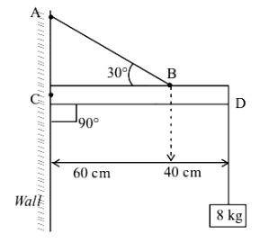
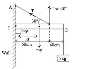
An object of mass 8 kg is hanging from one end of a uniform rod CD of mass 2 kg and length 1 m pivoted at its end C on a vertical wall as shown in figure. It is supported by a cable AB such that the system is in equilibrium. The tension in the cable is (Take \(g =10 m / s ^2\) ) [JEE Main 2023 (Online) 25th January Morning Shift]
 CorrectIncorrect
Hint
(d)

Step 1: Calculate the weights of the rod and hanging mass
The weight of the uniform rod ( \(W _{\text {rod }}\) ) acts at its center of mass (midpoint).
\(
W_{rod}=m_{rod} \times g=2 kg \times 10 m / s^2=20 N
\)
The weight of the hanging mass ( \(W _{\text {mass }}\) ) acts at end D.
\(
W_{\text {mass }}=m_{\text {mass }} \times g=8 kg \times 10 m / s^2=80 N
\)
Step 2: Determine torques about the pivot point C
For the system to be in rotational equilibrium, the sum of all torques about the pivot point C must be zero. We take counter-clockwise torques as positive. The weights of the rod and mass produce clockwise torques. The tension in the cable produces a counter-clockwise torque.
The distance to the rod’s center of mass is \(d_{\text {rod }}=1 m / 2=0.5 m\).
Torque due to the rod:
\(
\tau_{\text {rod }}=W_{\text {rod }} \times d_{\text {rod }}=20 N \times 0.5 m=10 Nm
\)
The distance to the hanging mass is \(d_{\text {mass }}=1 m\).
Torque due to the mass:
\(
\tau_{\text {mass }}=W_{\text {mass }} \times d_{\text {mass }}=80 N \times 1 m=80 Nm
\)
The cable attaches at point \(B\), which we assume is 60 cm or 0.6 m from the pivot \(C\) to match the problem’s intended solution. The tension \(T\) makes an angle of \(30^{\circ}\) with the rod (or horizontal in the typical diagram). The perpendicular distance from the pivot C to the line of action of the tension is
\(
r_{\perp}=r \sin (\theta)=0.6 m \times \sin \left(30^{\circ}\right)=0.6 m \times 0.5=0.3 m .
\)
Torque due to tension:
\(
\tau_{\text {tension }}=T \times r_{\perp}=T \times 0.3 m
\)
Step 3: Apply the equilibrium condition and solve for tension
For equilibrium, the sum of torques is zero:
\(
\begin{gathered}
\sum \tau_C=\tau_{\text {tension }}-\tau_{\text {rod }}-\tau_{\text {mass }}=0 \\
T \times 0.3 m-10 Nm-80 Nm=0 \\
T \times 0.3 m=90 Nm \\
T=\frac{90 Nm}{0.3 m} \\
T=300 N
\end{gathered}
\) - Question 25 of 72
25. Question
The torque of a force \(5 \hat{i}+3 \hat{j}-7 \hat{k}\) about the origin is \(\tau\). If the force acts on a particle whose position vector is \(2 i+2 j+k\), then the value of \(\tau\) will be [JEE Main 2022 (Online) 29th July Evening Shift]
CorrectIncorrectHint
(c) Step 1: Define Variables and Formula
The torque \(\vec{\tau}\) is calculated using the cross product of the position vector \(\vec{r}\) and the force vector \(\vec{F}\), given by the formula \(\vec{\tau}=\vec{r} \times \vec{F}\).
The given vectors are \(\vec{r}=2 \hat{i}+2 \hat{j}+1 \hat{k}\) and \(\vec{F}=5 \hat{i}+3 \hat{j}-7 \hat{k}\).
Step 2: Calculate the Cross Product
The cross product is computed as a determinant:
\(
\vec{\tau}=\left|\begin{array}{ccc}
\hat{i} & \hat{j} & \hat{k} \\
2 & 2 & 1 \\
5 & 3 & -7
\end{array}\right|
\)
\(
\vec{\tau}=-17 \hat{i}+19 \hat{j}-4 \hat{k}
\) - Question 26 of 72
26. Question
A solid cylinder and a solid sphere, having same mass \(M\) and radius \(R\), roll down the same inclined plane from top without slipping. They start from rest. The ratio of velocity of the solid cylinder to that of the solid sphere, with which they reach the ground, will be : [JEE Main 2022 (Online) 25th July Morning Shift]
CorrectIncorrectHint
(d) To find the ratio of the velocities of a solid cylinder and a solid sphere reaching the ground, we use the principle of conservation of mechanical energy for objects rolling without slipping.
STep 1: Physics Principles
When an object of mass \(M\) and radius \(R\) rolls down an incline of height \(h\) from rest, its initial potential energy is converted into both translational and rotational kinetic energy.
\(
M g h=\frac{1}{2} M v^2+\frac{1}{2} I \omega^2
\)
For rolling without slipping, \(\omega=v / R\). The moment of inertia \(I\) can be expressed as \(I= M K^2\), where \(K\) is the radius of gyration. The energy equation simplifies to:
\(
v=\sqrt{\frac{2 g h}{1+\frac{K^2}{R^2}}}
\)
Step 2: Identify Moments of Inertia and \(K^2 / R^2\)
We need the specific values for a solid cylinder and a solid sphere:
Solid Cylinder:
\(I_{\text {cyl }}=\frac{1}{2} M R^2\)
\(\frac{K_{c t}^2}{R^2}=\frac{1}{2}\)
Solid Sphere:
\(I_{\text {sph }}=\frac{2}{5} M R^2\)
\(\frac{K_{\text {ghh }}^2}{R^2}=\frac{2}{5}\)
Step 3: Calculate the Velocities
Substituting the values into the velocity formula:
Velocity of Cylinder ( \(v_{\text {cyl }}\) ):
\(
v_{c y l}=\sqrt{\frac{2 g h}{1+1 / 2}}=\sqrt{\frac{2 g h}{3 / 2}}=\sqrt{\frac{4 g h}{3}}
\)
Velocity of Sphere ( \(v_{\text {sph }}\) ):
\(
v_{s p h}=\sqrt{\frac{2 g h}{1+2 / 5}}=\sqrt{\frac{2 g h}{7 / 5}}=\sqrt{\frac{10 g h}{7}}
\)
Step 4: Determine the Ratio
The ratio of the velocity of the solid cylinder to that of the solid sphere is:
\(
\begin{gathered}
\frac{v_{c y l}}{v_{s p h}}=\frac{\sqrt{\frac{4 g h}{3}}}{\sqrt{\frac{10 g h}{7}}}=\sqrt{\frac{4}{3} \times \frac{7}{10}} \\
\frac{v_{c y l}}{v_{s p h}}=\sqrt{\frac{28}{30}}=\sqrt{\frac{14}{15}}
\end{gathered}
\) - Question 27 of 72
27. Question
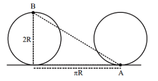
A spherical shell of 1 kg mass and radius \(R\) is rolling with angular speed \(\omega\) on horizontal plane (as shown in figure). The magnitude of angular momentum of the shell about the origin O is \(\frac{a}{3} R^2 \omega\). The value of a will be : [JEE Main 2022 (Online) 29th June Morning Shift]
 CorrectIncorrect
Hint
(d) To find the value of \(a\), we must calculate the total angular momentum of the rolling spherical shell about the origin \(O\).
Step 1: Physics Principles
The angular momentum \(L\) of a body performing rolling motion about a fixed point (the origin \(O\) ) is the sum of two components:
Angular momentum due to translation of the center of mass: \(L_{c m}=r \times M v_{c m}\).
Angular momentum due to rotation about the center of mass: \(L_{\text {rot }}=I_{c m} \omega\).
For a body rolling in the direction shown, both components of angular momentum point in the same direction (into the page or along the same axis), so we can add their magnitudes.
\(
L_{t o t a l}=M v_{c m} R+I_{c m} \omega
\)
Step 2: Properties of the Spherical Shell
We are given the following information:
Mass (\(M\)): 1 kg .
Moment of Inertia ( \(I_{c m}\) ): For a thin spherical shell (hollow sphere), \(I=\frac{2}{3} M R^2\).
Pure Rolling Condition: For rolling without slipping, the velocity of the center of mass is \(v_{c m}=R \omega\).
Step 3: Step-by-Step Calculation
Substitute the known values into the total angular momentum equation:
(i) Translational Component:
\(
L_{\text {trans }}=M(R \omega) R=M R^2 \omega
\)
(ii) Rotational Component:
\(
L_{\text {rot }}=\left(\frac{2}{3} M R^2\right) \omega=\frac{2}{3} M R^2 \omega
\)
(iii) Total Angular Momentum:
\(
\begin{gathered}
L_{\text {total }}=M R^2 \omega+\frac{2}{3} M R^2 \omega \\
L_{\text {total }}=\left(1+\frac{2}{3}\right) M R^2 \omega=\frac{5}{3} M R^2 \omega
\end{gathered}
\)
Step 4: Solve for \(a\)
Given the mass \(M=1 kg\), the expression becomes:
\(
L_{\text {total }}=\frac{5}{3}(1) R^2 \omega=\frac{5}{3} R^2 \omega
\)
Comparing this with the given form \(\frac{a}{3} R^2 \omega\) :
\(
\frac{5}{3} R^2 \omega=\frac{a}{3} R^2 \omega
\)
Therefore, \(a=5\). - Question 28 of 72
28. Question
A ball is spun with angular acceleration \(\alpha=6 t ^2-2 t\) where t is in second and \(\alpha\) is in rads \({ }^{-2}\). At \(t =0\), the ball has angular velocity of \(10 rads ^{-1}\) and angular position of 4 rad. The most appropriate expression for the angular position of the ball is : [JEE Main 2022 (Online) 28th June Evening Shift]
CorrectIncorrectHint
(b) To find the most appropriate expression for the angular position \(\theta(t)\), we must integrate the given angular acceleration \(\alpha(t)\) twice with respect to time.
Step 1: Integrate angular acceleration to find angular velocity
The angular acceleration is given by \(\alpha(t)=6 t^2-2 t\). Integrating with respect to time gives the angular velocity \(\omega(t)\) :
\(
\omega(t)=\int \alpha(t) d t=\int\left(6 t^2-2 t\right) d t=2 t^3-t^2+C_1
\)
Using the initial condition \(\omega(0)=10 rads ^{-1}\), we find \(C_1\) :
\(
10=2(0)^3-(0)^2+C_1 \Longrightarrow C_1=10
\)
So the angular velocity expression is \(\omega(t)=2 t^3-t^2+10\).
Step 2: Integrate angular velocity to find angular position
Integrating the angular velocity \(\omega(t)\) with respect to time gives the angular position \(\theta(t)\) :
\(
\theta(t)=\int \omega(t) d t=\int\left(2 t^3-t^2+10\right) d t=\frac{t^4}{2}-\frac{t^3}{3}+10 t+C_2
\)
Using the initial condition \(\theta(0)=4 rad\), we find \(C_2\) :
\(
4=\frac{(0)^4}{2}-\frac{(0)^3}{3}+10(0)+C_2 \Longrightarrow C_2=4
\)
So the angular position expression is \(\theta(t)=\frac{t^4}{2}-\frac{t^3}{3}+10 t+4\). - Question 29 of 72
29. Question
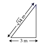
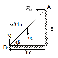
A \(\sqrt{34} m\) long ladder weighing 10 kg leans on a frictionless wall. Its feet rest on the floor 3 m away from the wall as shown in the figure. If \(F _{ f }\) and \(F _{ w }\) are the reaction forces of the floor and the wall, then ratio of \(F_w / F_f\) will be : [JEE Main 2022 (Online) 28th June Evening Shift]
(Use \(g =10 m / s ^2\).) CorrectIncorrect
Hint
(c)

\(
\begin{aligned}
&\text { Taking torque from B }\\
&\begin{aligned}
& F_w \times 5=\frac{3}{2} m g \\
& \Rightarrow F_w=\frac{3}{10} \times 10 \times 10 \\
& =30 N \\
& N=m g=100 N \\
& \text { and } f_r=F_w=30 N \\
& \text { so } F_f=\sqrt{N^2+f_r^2}=\sqrt{10900}=10 \sqrt{109} N \\
& \text { so } \frac{F_w}{F_f}=\frac{3}{\sqrt{109}}
\end{aligned}
\end{aligned}
\) - Question 30 of 72
30. Question
Match List-I with List-II
\(
\begin{array}{|l|l|}
\hline \text { List – I } & \text { List – II } \\
\hline \text { A. Moment of inertia of a solid sphere of radius } R \text { about any tangent. } & \text { 1. } \frac{5}{3} M R^2 \\
\hline \text { B. Moment of inertia of a hollow sphere of radius } R \text { about any tangent. } & \text { II. } \frac{7}{5} M R^2 \\
\hline \text { C. Moment of inertia of a circular ring of radius } R \text { about its diameter. } & \text { III. } \frac{1}{2} M R^2 \\
\hline \text { D. Moment of inertia of a circular disc of radius } R \text { about any diameter. } & \text { IV. } \frac{1}{4} M R^2 \\
\hline
\end{array}
\)
Choose the correct answer from the options given below : [JEE Main 2022 (Online) 28th June Morning Shift]CorrectIncorrectHint
(a)
A. Moment of inertia of a solid sphere about any tangent:
The moment of inertia of a solid sphere about its diameter is \(I_{c m}=\frac{2}{5} M R^2\).
According to the Parallel Axis Theorem ( \(I=I_{c m}+M d^2\) ), the distance \(d\) from the center to a tangent is \(R\).
\(I_{\text {tangent }}=\frac{2}{5} M R^2+M(R)^2=\frac{7}{5} M R ^2\).
Matches with II.
B. Moment of inertia of a hollow sphere about any tangent:
The moment of inertia of a hollow sphere (spherical shell) about its diameter is \(I_{c m}=\frac{2}{3} M R^2\).
Using the Parallel Axis Theorem with \(d=R\) :
\(I_{\text {tangent }}=\frac{2}{3} M R^2+M(R)^2=\frac{5}{3} M R ^2\).
Matches with I.
C. Moment of inertia of a circular ring about its diameter:
The moment of inertia of a ring about its central axis (perpendicular to its plane) is \(I_z=M R^2\).
Using the Perpendicular Axis Theorem ( \(I_z=I_x+I_y\) ), where \(I_x\) and \(I_y\) are moments of inertia about two perpendicular diameters \(\left(I_x=I_y=I_{\text {dia }}\right)\) :
\(M R^2=2 I_{\text {dia }} \Longrightarrow I_{\text {dia }}=\frac{1}{2} M R ^2\).
Matches with IV.
D. Moment of inertia of a circular disc about any diameter:
The moment of inertia of a disc about its central axis (perpendicular to its plane) is \(I_z=\frac{1}{2} M R^2\).
Using the Perpendicular Axis Theorem ( \(I_z=2 I_{\text {dia }}\) ):
\(\frac{1}{2} M R^2=2 I_{\text {dia }} \Longrightarrow I_{\text {dia }}=\frac{1}{4} M R ^2\).
Matches with III. - Question 31 of 72
31. Question
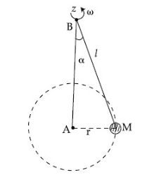
One end of a massless spring of spring constant \(k\) and natural length \(l _0\) is fixed while the other end is connected to a small object of mass \(m\) lying on a frictionless table. The spring remains horizontal on the table. If the object is made to rotate at an angular velocity \(\omega\) about an axis passing through fixed end, then the elongation of the spring will be : [JEE Main 2022 (Online) 27th June Evening Shift]
CorrectIncorrectHint
(c) To find the elongation of the spring, we must analyze the forces acting on the mass \(m\) in a rotating frame of reference or using centripetal force requirements.
Step 1: When the mass \(m\) rotates at an angular velocity \(\omega\), it follows a circular path. The required centripetal force for this circular motion is provided by the spring force.
Natural length of the spring: \(l_0\)
Elongation of the spring: Let this be \(x\).
New length of the spring (Radius of rotation, \(r\) ): \(r=l_0+x\).
Spring Force \(\left(F_s\right): F_s=k x\) (where \(k\) is the spring constant).
Centripetal Force \(\left(F_c\right): F_c=m r \omega^2=m\left(l_0+x\right) \omega^2\).
Step 2: Setting up the Equilibrium Equation
For the mass to maintain its circular path at a constant radius, the spring force must equal the required centripetal force:
\(
k x=m\left(l_0+x\right) \omega^2
\)
Step 3: Solving for Elongation ( \(x\) )
\(
k x=m l_0 \omega^2+m x \omega^2
\)
\(
x=\frac{m l_0 \omega^2}{k-m \omega^2}
\)
The elongation of the spring is \(\frac{m \omega^2 l_0}{k-m \omega^2}\). - Question 32 of 72
32. Question
A solid spherical ball is rolling on a frictionless horizontal plane surface about its axis of symmetry. The ratio of rotational kinetic energy of the ball to its total kinetic energy is [JEE Main 2022 (Online) 26th June Evening Shift]
CorrectIncorrectHint
(b) Step 1: Define physical quantities and formulas
The translational kinetic energy ( \(K _{\text {trans }}\) ), rotational kinetic energy ( \(K _{\text {rot }}\) ), and total kinetic energy ( \(K _{\text {total }}\) ) are given by the formulas:
\(
\begin{gathered}
K_{t r a n s}=\frac{1}{2} m v^2 \\
K_{r o t}=\frac{1}{2} I \omega^2 \\
K_{t o t a l}=K_{t r a n s}+K_{r o t}
\end{gathered}
\)
For a solid sphere, the moment of inertia \(I\) is:
\(
I=\frac{2}{5} m r^2
\)
Assuming the ball is rolling without slipping (standard assumption for such problems), the linear velocity \(v\) and angular velocity \(\omega\) are related by:
\(
v=\omega r
\)
Step 2: Calculate the ratio
Substitute \(I\) and \(\omega=\frac{v}{r}\) into the rotational kinetic energy equation:
\(
K_{r o t}=\frac{1}{2}\left(\frac{2}{5} m r^2\right) \omega^2=\frac{1}{5} m r^2\left(\frac{v}{r}\right)^2=\frac{1}{5} m v^2
\)
The total kinetic energy is:
\(
K_{\text {total }}=\frac{1}{2} m v^2+\frac{1}{5} m v^2=\left(\frac{1}{2}+\frac{1}{5}\right) m v^2=\left(\frac{5+2}{10}\right) m v^2=\frac{7}{10} m v^2
\)
The ratio of rotational kinetic energy to total kinetic energy is:
\(
\frac{K_{r o t}}{K_{t o t a l}}=\frac{\frac{1}{5} m v^2}{\frac{7}{10} m v^2}=\frac{1}{5} \times \frac{10}{7}=\frac{10}{35}=\frac{2}{7}
\) - Question 33 of 72
33. Question
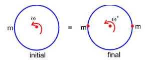
A thin circular ring of mass \(M\) and radius \(R\) is rotating with a constant angular velocity 2 rads \(^{-1}\) in a horizontal plane about an axis vertical to its plane and passing through the center of the ring. If two objects each of mass \(m\) be attached gently to the opposite ends of a diameter of ring, the ring will then rotate with an angular velocity (in rads \({ }^{-1}\) ). [JEE Main 2022 (Online) 26th June Morning Shift]
CorrectIncorrectHint
(c)

By conservation of Angular momentum
\(L_i = L_f\)
\(
\begin{aligned}
M R^2 \omega & =\left(m R^2+2 m R^2\right) \omega^{\prime} \\
\frac{2 M}{M+2 m} & =\omega^{\prime} \\
\Rightarrow \omega^{\prime} & =\frac{2 M}{M+2 m}
\end{aligned}
\)Explanation: To solve this problem, we apply the Principle of Conservation of Angular Momentum. Because the two objects are attached “gently,” no external torque acts on the system about the vertical axis of rotation. Therefore, the initial angular momentum must equal the final angular momentum.
Step 1: Initial State
Initially, the system consists only of the thin circular ring rotating about its central vertical axis.
Moment of Inertia of the Ring \(\left(I_i\right)\) : \(I_{\text {ring }}=M R^2\).
Initial Angular Velocity \(\left(\omega_i\right): 2 rad s ^{-1}\).
Initial Angular Momentum \(\left(L_i\right): L_i=I_i \omega_i=\left(M R^2\right)(2)=2 M R^2\).
Step 2: Final State
Two objects, each of mass \(m\), are attached to opposite ends of a diameter. These objects are at a distance \(R\) from the axis of rotation.
Final Moment of Inertia \(\left(I_f\right)\) : This is the sum of the moment of inertia of the ring and the two point masses.
\(I_f=I_{\text {ring }}+2 \times\left(m R^2\right)\)
\(I_f=M R^2+2 m R^2=(M+2 m) R^2\)
Final Angular Velocity \(\left(\omega_f\right)\) : This is the value we need to find.
Step 3: Conservation of Angular Momentum Calculation
Equating the initial and final angular momentum:
\(
\begin{gathered}
L_i=L_f \\
I_i \omega_i=I_f \omega_f
\end{gathered}
\)
Substitute the known expressions:
\(
\left(M R^2\right)(2)=(M+2 m) R^2 \cdot \omega_f
\)
Cancel \(R^2\) from both sides:
\(
2 M=(M+2 m) \cdot \omega_f
\)
Solve for \(\omega_f\) :
\(
\omega_f=\frac{2 M}{M+2 m}
\) - Question 34 of 72
34. Question
If force \(\vec{F}=3 \hat{i}+4 \hat{j}-2 \hat{k}\) acts on a particle position vector \(2 \hat{i}+\hat{j}+2 \hat{k}\) then, the torque about the origin will be : [JEE Main 2022 (Online) 25th June Morning Shift]
CorrectIncorrectHint
(b) The torque \((\vec{\tau})\) about the origin is calculated using the cross product of the position vector \((\vec{r})\) and the force vector \((\overrightarrow{ F })\) :
\(
\vec{\tau}=\vec{r} \times \vec{F}
\)
Given:
\(\vec{r}=2 \hat{i}+1 \hat{j}+2 \hat{k}\)
\(\vec{F}=3 \hat{i}+4 \hat{j}-2 \hat{k}\)
We calculate the cross product using a determinant:
\(
\vec{\tau}=\left|\begin{array}{ccc}
\hat{i} & \hat{j} & \hat{k} \\
2 & 1 & 2 \\
3 & 4 & -2
\end{array}\right|
\)
\(
\vec{\tau}=-10 \hat{i}+10 \hat{j}+5 \hat{k}
\) - Question 35 of 72
35. Question
A system consists of two identical spheres each of mass 1.5 kg and radius 50 cm at the end of light rod. The distance between the centres of the two spheres is 5 m. What will be the moment of inertia of the system about an axis perpendicular to the rod passing through its midpoint? [JEE Main 2021 (Online) 31st August Evening Shift]
CorrectIncorrectHint
(c)

To find the moment of inertia of the system about an axis perpendicular to the rod passing through its midpoint, we must consider the contribution of each sphere and apply the Parallel Axis Theorem.
Step 1: Identify System Parameters
Mass of each sphere ( \(M\) ): 1.5 kg .
Radius of each sphere \((R)\) : \(50 cm=0.5 m\).
Distance between centers \(\left(d_{\text {total }}\right): 5 m\).
Distance from midpoint to center of each sphere \((d): \frac{5}{2}=2.5 m\).
Step2: Moment of Inertia of One Sphere
First, we find the moment of inertia of a single solid sphere about its own center of mass \(\left(I_{c m}\right)\) :
\(
\begin{gathered}
I_{c m}=\frac{2}{5} M R^2=\frac{2}{5}(1.5)(0.5)^2 \\
I_{c m}=0.4 \times 1.5 \times 0.25=0.15 kg \cdot m^2
\end{gathered}
\)
Next, we use the Parallel Axis Theorem ( \(I=I_{c m}+M d^2\) ) to find the moment of inertia of one sphere about the midpoint axis:
\(
\begin{gathered}
I_{\text {sphere }}=0.15+(1.5)(2.5)^2 \\
I_{\text {sphere }}=0.15+(1.5)(6.25)=0.15+9.375=9.525 kg \cdot m^2
\end{gathered}
\)
Step 3: Total Moment of Inertia of the System
Since the system consists of two identical spheres placed symmetrically about the midpoint, the total moment of inertia ( \(I_{\text {total }}\) ) is the sum of the moments of inertia of both spheres:
\(
\begin{gathered}
I_{\text {total }}=2 \times I_{\text {sphere }} \\
I_{\text {total }}=2 \times 9.525=19.05 kg \cdot m^2
\end{gathered}
\)
The moment of inertia of the system about the midpoint axis is \(19.05 kg \cdot m ^2\). - Question 36 of 72
36. Question
Angular momentum of a single particle moving with constant speed along circular path : [JEE Main 2021 (Online) 31st August Morning Shift]
CorrectIncorrectHint
(b)

The angular momentum ( \(L=\vec{r} \times \vec{p}\) ) of a single particle moving with constant speed along a circular path remains the same in both magnitude ( \(L=m v r\) ) and direction (perpendicular to the plane of motion) because the distance \(r\) from the center and speed \(v\) are constant.
Correct Answer: B (remains same in magnitude and direction).
Explanation: To determine the angular momentum of a particle moving with constant speed along a circular path, we must evaluate both its magnitude and its direction based on rotational dynamics.
Step 1: Magnitude of Angular Momentum
For a particle of mass \(M\) moving in a circle of radius \(R\) with constant speed \(v\) :
The angular momentum magnitude ( \(L\) ) is given by the formula \(L=M v r \sin \theta\).
In a circular path, the velocity vector \(v\) is always perpendicular to the position vector \(r\) (the radius), meaning \(\theta=90^{\circ}\).
Since \(M\), and \(R\) are all constant, the magnitude \(L=M v R\) remains same.
Step 2: Direction of Angular Momentum
The direction of the angular momentum vector \(L\) is defined by the cross product:
\(
L=r \times p=r \times(M v)
\)
According to the right-hand rule, the direction of \(L\) is perpendicular to the plane containing the radius and the velocity vector.
For a particle moving in a fixed circular path (in a single plane), the direction of \(L\) points along the axis of rotation.
As long as the particle continues to rotate in the same sense (e.g., counter-clockwise) in the same plane, the direction of the vector remains same.
Step 3: Conclusion
Since both the speed and the radius are constant, and the motion is confined to a fixed plane, the angular momentum vector does not change in size or orientation. - Question 37 of 72
37. Question
Two discs have moments of inertia \(I _1\) and \(I _2\) about their respective axes perpendicular to the plane and passing through the centre. They are rotating with angular speeds, \(\omega_1\) and \(\omega_2\) respectively and are brought into contact face to face with their axes of rotation coaxial. The loss in kinetic energy of the system in the process is given by : [JEE Main 2021 (Online) 27th August Evening Shift]
CorrectIncorrectHint
(c)

To determine the loss in kinetic energy when two rotating discs are brought into contact face-to-face, we use the principle of Conservation of Angular Momentum followed by calculating the change in rotational kinetic energy.
Step 1: Conservation of Angular Momentum
When the two discs are brought into contact and rotate coaxially, there is no external torque acting on the system. Therefore, the total initial angular momentum ( \(L_i\) ) must equal the total final angular momentum ( \(L_f\) ).
Initial Angular Momentum \(\left(L_i\right): L_i=I_1 \omega_1+I_2 \omega_2\).
Final Angular Momentum ( \(L_f\) ): Since they rotate together after contact with a common angular velocity \(\omega, L_f=\left(I_1+I_2\right) \omega\).
Equating the two to find the common angular velocity:
\(
\left(I_1+I_2\right) \omega=I_1 \omega_1+I_2 \omega_2 \Longrightarrow \omega=\frac{I_1 \omega_1+I_2 \omega_2}{I_1+I_2}
\)
Step 2: Calculation of Kinetic Energy Loss
The loss in kinetic energy ( \(\Delta K\) ) is the difference between the initial total kinetic energy and the final total kinetic energy of the system.
Initial Kinetic Energy \(\left(K_i\right): K_i=\frac{1}{2} I_1 \omega_1^2+\frac{1}{2} I_2 \omega_2^2\).
Final Kinetic Energy \(\left(K_f\right)\) : \(K_f=\frac{1}{2}\left(I_1+I_2\right) \omega^2\).
Substituting the expression for common angular velocity \(\omega\) into \(K_f\) :
\(
K_f=\frac{1}{2}\left(I_1+I_2\right)\left(\frac{I_1 \omega_1+I_2 \omega_2}{I_1+I_2}\right)^2=\frac{1}{2} \frac{\left(I_1 \omega_1+I_2 \omega_2\right)^2}{I_1+I_2}
\)
Step 3: Simplified Expression for Energy Loss
The energy loss is calculated as \(\Delta K=K_i-K_f\) :
\(
\Delta K=\left[\frac{1}{2} I_1 \omega_1^2+\frac{1}{2} I_2 \omega_2^2\right]-\left[\frac{1}{2} \frac{\left(I_1 \omega_1+I_2 \omega_2\right)^2}{I_1+I_2}\right]
\)
After expanding the numerator and finding a common denominator, the expression simplifies to:
\(
\Delta K=\frac{I_1 I_2\left(\omega_1-\omega_2\right)^2}{2\left(I_1+I_2\right)}
\)
This loss in energy is dissipated as heat due to friction between the surfaces as they slide against each other until their speeds synchronize.
Final Answer: The correct expression is (C) \(\frac{I_1 I_2}{2\left(I_1+I_2\right)}\left(\omega_1-\omega_2\right)^2\). - Question 38 of 72
38. Question
Moment of inertia of a square plate of side \(l\) about the axis passing through one of the corner and perpendicular to the plane of square plate is given by : [JEE Main 2021 (Online) 27th August Morning Shift]
CorrectIncorrectHint
(d)

To find the moment of inertia of a square plate about an axis passing through one of its corners and perpendicular to its plane, we apply the standard formula for a square plate and the Parallel Axis Theorem.
Step 1: Moment of Inertia about the Center of Mass
For a square plate of mass \(M\) and side length \(l\), the moment of inertia about an axis passing through its center of mass ( \(C M\) ) and perpendicular to its plane is:
\(
I_{c m}=\frac{M\left(l^2+l^2\right)}{12}=\frac{2 M l^2}{12}=\frac{M l^2}{6}
\)
Step 2: Distance to the Corner
The distance ( \(d\) ) from the center of the square to any of its corners is half the length of the diagonal.
The diagonal of a square with side \(l\) is \(l \sqrt{2}\).
The distance \(d\) is therefore:
\(
d=\frac{l \sqrt{2}}{2}=\frac{l}{\sqrt{2}}
\)
Step 3: Applying the Parallel Axis Theorem
The Parallel Axis Theorem states that \(I=I_{c m}+M d^2\). Substituting the values for \(I_{c m}\) and \(d\) :
\(
\begin{gathered}
I_{\text {corner }}=\frac{M l^2}{6}+M\left(\frac{l}{\sqrt{2}}\right)^2 \\
I_{\text {corner }}=\frac{M l^2}{6}+\frac{M l^2}{2}
\end{gathered}
\)
To add these, we use a common denominator:
\(
\begin{gathered}
I_{\text {corner }}=\frac{M l^2+3 M l^2}{6}=\frac{4 M l^2}{6} \\
I_{\text {corner }}=\frac{2}{3} M l^2
\end{gathered}
\)
The moment of inertia about the axis passing through the corner is \(\frac{2}{3} M l^2\). - Question 39 of 72
39. Question
The solid cylinder of length 80 cm and mass M has a radius of 20 cm . Calculate the density of the material used if the moment of inertia of the cylinder about an axis \(C D\) parallel to \(A B\) as shown in figure is \(2.7 kg m ^2\). [JEE Main 2021 (Online) 26th August Evening Shift]
 CorrectIncorrect
Hint
(d)
\(
\begin{aligned}
&\text { Parallel axis theorem }\\
&\begin{aligned}
& I=I_{C M}+M d^2 \\
& I=\frac{M r^2}{2}+M\left(\frac{L}{2}\right)^2 \\
& 2.7=M \frac{(0.2)^2}{2}+M\left(\frac{0.8}{2}\right)^2 \\
& 2.7=M\left[\frac{2}{100}+\frac{16}{100}\right] \\
& M=15 kg \\
& \Rightarrow \rho=\frac{M}{\pi r^2 L}=\frac{15}{\pi(0.2)^2 \times 0.8} \\
& =0.1492 \times 10^3
\end{aligned}
\end{aligned}
\)Explanation: Step 1: Identify the Moments of Inertia and Geometry
From the image and the principles of rotational dynamics, we identify the following:
Axis AB (Center of Mass): For a solid cylinder of mass \(M\) and radius \(R\), the moment of inertia about its longitudinal axis is \(I_{c m}=\frac{1}{2} M R^2\).
Axis CD (Parallel Axis): This axis is parallel to \(A B\) at a distance \(d\). According to the provided figure, the distance between the two axes is \(d=L / 2\).
Given Values:
Length \((L)=80 cm=0.8 m\).
Radius \((R)=20 cm=0.2 m\).
Distance \((d)=L / 2=40 cm=0.4 m\).
Moment of Inertia \(\left(I_{C D}\right)=2.7 kg m ^2\).
Step 2: Apply the Parallel Axis Theorem
To find the mass \((M)\), we use the Parallel Axis Theorem: \(I=I_{c m}+M d^2\).
\(
I_{C D}=\frac{1}{2} M R^2+M\left(\frac{L}{2}\right)^2
\)
Substitute the known values:
\(
2.7=\frac{1}{2} M(0.2)^2+M(0.4)^2
\)
\(
M=\frac{2.7}{0.18}=15 kg
\)
Step 3: Calculate the Density ( \(\rho\) )
Density is defined as the mass per unit volume ( \(\rho=M / V\) ).
Step A: Calculate Volume ( \(V\) ) For a cylinder, the volume is \(V=\pi R^2 L\) :
\(
\begin{gathered}
V=\pi \times(0.2)^2 \times 0.8 \\
V=\pi \times 0.04 \times 0.8=0.032 \pi m^3
\end{gathered}
\)
Step B: Final Density Calculation
\(
\begin{gathered}
\rho=\frac{15}{0.032 \pi} \\
\rho \approx \frac{15}{0.10053} \\
\rho \approx 149.21 kg / m^3
\end{gathered}
\)
Final Answer: The density of the material used is approximately \(149.21 kg / m ^3\). - Question 40 of 72
40. Question
Match List-I with List-II:
\(
\begin{array}{|l|l|}
\hline \text { List-I } & \text { List-II } \\
\hline \text { (a) MI of the rod (length L, Mass M, about an axis ⟂ to the rod passing through the midpoint) } & \text { (i) } 8 M L^2 / 3 \\
\hline \text { (b) MI of the rod (length L, Mass } 2 M \text {, about an axis ⟂ to the rod passing through one of its end) } & \text { (ii) } M L^2 / 3 \\
\hline \text { (c) MI of the rod (length } 2 L, \text { Mass M, about an axis } \perp \text { to the rod passing through its midpoint) } & \text { (iii) } M L^2 / 12 \\
\hline \text { (d) MI of the rod (Length } 2 L, \text { Mass } 2 M \text {, about an axis ⟂ to the rod passing through one of its end) } & \text { (iv) } 2 M L^2 / 3 \\
\hline
\end{array}
\)
Choose the correct answer from the options given below: [JEE Main 2021 (Online) 27th July Morning Shift]CorrectIncorrectHint
(c)

Formula Reference:
For a uniform rod of mass \(M\) and length \(L\) :
About its midpoint (perpendicular axis): \(I=\frac{1}{12} M L^2\).
About one of its ends (perpendicular axis): \(I=\frac{1}{3} M L^2\).
Step-by-Step Analysis of List-I
(a) MI of rod (Length \(L\), Mass \(M\), axis ⟂ through midpoint): Using the standard formula for mass \(M\) and length \(L\) :
\(
I_a=\frac{1}{12} M L^2
\)
Matches with (iii).
(b) MI of rod (Length \(L\), Mass \(2 M\), axis ⟂ through one end): Substitute mass \(2 M\) into the end-axis formula:
\(
I_b=\frac{1}{3}(2 M) L^2=\frac{2}{3} M L^2
\)
Matches with (iv).
(c) MI of rod (Length \(2 L\), Mass \(M\), axis ⟂ through midpoint): Substitute length \(2 L\) into the midpoint-axis formula:
\(
I_c=\frac{1}{12} M(2 L)^2=\frac{1}{12} M\left(4 L^2\right)=\frac{1}{3} M L^2
\)
Matches with (ii).
(d) MI of rod (Length \(2 L\), Mass \(2 M\), axis ⟂ through one end): Substitute mass \(2 M\) and length \(2 L\) into the end-axis formula:
\(
I_d=\frac{1}{3}(2 M)(2 L)^2=\frac{1}{3}(2 M)\left(4 L^2\right)=\frac{8}{3} M L^2
\)
Matches with (i). - Question 41 of 72
41. Question
The figure shows two solid discs with radius \(R\) and \(r\) respectively. If mass per unit area is same for both, what is the ratio of MI of bigger disc around axis AB (Which is ⟂ to the plane of the disc and passing through its centre) of MI of smaller disc around one of its diameters lying on its plane? Given ‘ \(M\) ‘ is the mass of the larger disc. (MI stands for moment of inertia) [JEE Main 2021 (Online) 27th July Morning Shift]
 CorrectIncorrect
Hint
(d) To find the ratio of the moments of inertia (MI), we first need to establish the relationship between the masses of the two discs based on the constant mass per unit area ( \(\sigma\) ).
Step 1: Relationship Between Masses
The mass per unit area is defined as \(\sigma=\frac{\text { Mass }}{\text { Area }}\).
For the larger disc: \(M=\sigma\left(\pi R^2\right)\)
For the smaller disc: \(m=\sigma\left(\pi r^2\right)\)
By taking the ratio:
\(
\frac{m}{M}=\frac{\sigma \pi r^2}{\sigma \pi R^2} \Longrightarrow m=M \frac{r^2}{R^2}
\)
Step 2: Calculating Moments of Inertia
We need to calculate the MI for each disc according to the specific axes described:
Bigger Disc \(\left(I_B\right)\) : The axis AB is perpendicular to the plane and passes through the center.
\(
I_B=\frac{1}{2} M R^2
\)
Smaller Disc \(\left(I_s\right)\) : The axis is a diameter lying on its plane.
\(
I_s=\frac{1}{4} m r^2
\)
Step 3: Finding the Ratio
Now, we substitute the expression for \(m\) (from step 1) into the equation for \(I_s\) :
\(
I_s=\frac{1}{4}\left(M \frac{r^2}{R^2}\right) r^2=\frac{M r^4}{4 R^2}
\)
Finally, we calculate the ratio of \(I_B\) to \(I_s\) :
\(
\text { Ratio }=\frac{I_B}{I_s}=\frac{\frac{1}{2} M R^2}{\frac{M r^4}{4 R^2}}
\)
Simplify the expression:
\(
\text { Ratio }=\frac{1}{2} M R^2 \cdot \frac{4 R^2}{M r^4}=\frac{4 R^4}{2 r^4}=2\left(\frac{R}{r}\right)^4
\)
Final Result
The ratio of the moment of inertia of the bigger disc to the smaller disc is:
\(
2:\left(\frac{r}{R}\right)^4 \text { or } 2\left(\frac{R}{r}\right)^4
\) - Question 42 of 72
42. Question
Given below are two statements : one is labelled as Assertion A and the other is labelled as Reason R.
Assertion A : Moment of inertia of a circular disc of mass ‘ M ‘ and radius ‘ R ‘ about \(X , Y\) axes (passing through its plane) and Z -axis which is perpendicular to its plane were found to be \(I _{ x }, I _{ y }\) and \(I _{ z }\) respectively. The respectively radii of gyration about all the three axes will be the same.
Reason R : A rigid body making rotational motion has fixed mass and shape. In the light of the above statements, choose the most appropriate answer from the options given below : [JEE Main 2021 (Online) 25th July Morning Shift]CorrectIncorrectHint
(b) Evaluation of Statements:
Assertion A: Incorrect The radius of gyration ( \(k\) ) is defined by the relation \(I=M k^2\), which means \(k=\sqrt{\frac{I}{M}}\). For a circular disc of mass \(M\) and radius \(R\) :
About the \(X\) and \(Y\) axes (diameters): The moment of inertia is \(I_x=I_y=\frac{1}{4} M R^2\). Thus, the radius of gyration is \(k_x=k_y=\sqrt{\frac{1}{4} R^2}=\frac{R}{2}\).
About the \(Z\)-axis (perpendicular through center): According to the perpendicular axis theorem \(\left(I_z=I_x+I_y\right)\), the moment of inertia is \(I_z=\frac{1}{2} M R^2\). Thus, the radius of gyration is \(k_z=\sqrt{\frac{1}{2} R^2}=\frac{R}{\sqrt{2}}\). Since \(\frac{R}{2} \neq \frac{R}{\sqrt{2}}\), the radii of gyration about all three axes are not the same.
Reason R: Correct By definition, a rigid body is an idealization of a solid body in which deformation is neglected. This implies that the distance between any two given points of the rigid body remains constant in time regardless of external forces exerted on it. Therefore, it has a fixed mass and shape during rotational motion.Conclusion: The most appropriate answer is: Assertion A is not correct but Reason R is correct.
- Question 43 of 72
43. Question
Consider a situation in which a ring, a solid cylinder and a solid sphere roll down on the same inclined plane without slipping. Assume that they start rolling from rest and having identical diameter.
The correct statement for this situation is [JEE Main 2021 (Online) 22th July Evening Shift]CorrectIncorrectHint
(c) To determine which object has the greatest velocity at the bottom of the inclined plane, we use the principle of conservation of energy or the specific formula for velocity in rolling motion.
Step 1: The Velocity Formula
When an object rolls down an inclined plane of height \(h\) without slipping, its velocity \(v\) at the bottom is given by:
\(
v=\sqrt{\frac{2 g h}{1+\frac{R^2}{R^2}}}
\)
where \(k\) is the radius of gyration and \(R\) is the radius of the object.
From this formula, we can see that velocity is inversely proportional to the factor \(\frac{k^2}{R^2}\). This means:
A smaller \(\frac{k^2}{R^2}\) results in a greater velocity.
A larger \(\frac{k^2}{R^2}\) results in a lower velocity.
Step 2: Comparing the Objects
The value of \(\frac{k^2}{R^2}\) is the coefficient in the formula for the Moment of Inertia \(\left(I=\beta M R^2\right.\), where \(\left.\beta=\frac{k^2}{R^2}\right):\)
\(
\begin{array}{llll}
\text { Object } & \text { Moment of Inertia }(I) & \frac{k^2}{R^2} \text { Value } & \text { Decimal } \\
\text { Solid Sphere } & \frac{2}{5} M R^2 & 0.4 & \text { Lowest } \\
\text { Solid Cylinder } & \frac{1}{2} M R^2 & 0.5 & \text { Intermediate } \\
\text { Ring } & M R^2 & 1.0 & \text { Highest }
\end{array}
\)
Step 3: Conclusion
Since the Solid Sphere has the smallest \(\frac{k^2}{R^2}(0.4)\), it will have the greatest velocity.
Since the Ring has the largest \(\frac{k^2}{R^2}(1.0)\), it will have the least velocity.
The sphere has the greatest and the ring has the least velocity of the centre of mass at the bottom of the inclined plane. - Question 44 of 72
44. Question
A body rolls down an inclined plane without slipping. The kinetic energy of rotation is 50% of its translational kinetic energy. The body is : [JEE Main 2021 (Online) 20th July Evening Shift]
CorrectIncorrectHint
(b) To determine which body has a rotational kinetic energy that is \(50 \%\) of its translational kinetic energy, we analyze the relationship between the two forms of energy during pure rolling (rolling without slipping).
Step 1: Formulas for Kinetic Energy
For a body of mass \(M\), radius \(R\), and moment of inertia \(I\), rolling with a linear velocity \(v\) and angular velocity \(\omega\) :
Translational Kinetic Energy \(\left(K_t\right): K_t=\frac{1}{2} M v^2\)
Rotational Kinetic Energy \(\left(K_r\right): K_r=\frac{1}{2} I \omega^2\)
In the case of pure rolling, we use the condition \(v=R \omega\) or \(\omega=\frac{v}{R}\). Substituting this into the rotational kinetic energy formula:
\(
K_r=\frac{1}{2} I\left(\frac{v}{R}\right)^2=\frac{I v^2}{2 R^2}
\)
Step 2: Setting Up the Condition
The problem states that \(K_r\) is \(50 \%\) (or \(\frac{1}{2}\) ) of \(K_t\) :
\(
\begin{gathered}
K_r=\frac{1}{2} K_t \Longrightarrow \frac{I v^2}{2 R^2}=\frac{1}{2}\left(\frac{1}{2} M v^2\right) \\
\frac{I}{2 R^2}=\frac{M}{4} \\
I=\frac{1}{2} M R^2
\end{gathered}
\)
Step 3: Comparing with Standard Bodies
We now match the calculated moment of inertia \(\left(I=\frac{1}{2} M R^2\right)\) with the given options:
\(
\begin{array}{lll}
\text { Body } & \text { Moment of Inertia }(I) & K_r \text { as \% of } K_t \\
\text { Solid Sphere } & \frac{2}{5} M R^2 & 40 \% \\
\text { Solid Cylinder } & \frac{1}{2} M R^2 & 50 \% \\
\text { Hollow Cylinder } & M R^2 & 100 \% \\
\text { Ring } & M R^2 & 100 \%
\end{array}
\)
The body whose rotational kinetic energy is exactly 50% of its translational kinetic energy is the Solid Cylinder. - Question 45 of 72
45. Question
Consider a uniform wire of mass M and length L. It is bent into a semicircle. Its moment of inertia about a line perpendicular to the plane of the wire passing through the center is : [JEE Main 2021 (Online) 18th March Evening Shift]
CorrectIncorrectHint
(d)

∴ From figure,
\(
\begin{aligned}
& L=\pi R \\
& \Rightarrow R=\frac{L}{\pi}
\end{aligned}
\)
Moment of inertia about center O,
\(
I=MR^2=M\left(\frac{L}{\pi}\right)^2=\frac{M L^2}{\pi^2}
\)Explanation: To find the moment of inertia of a uniform wire bent into a semicircle, we need to relate its length to its radius and then apply the definition of the moment of inertia.
Step 1: Relate Length ( \(L\) ) and Radius ( \(R\) )
A full circle of radius \(R\) has a circumference of \(2 \pi R\). Since the wire is bent into a semicircle, its length \(L\) is half of that circumference:
\(
L=\pi R
\)
Solving for the radius \(R\) in terms of \(L\) :
\(
R=\frac{L}{\pi}
\)
Step 2: Calculate Moment of Inertia (I)
The moment of inertia of any collection of point masses (or a continuous distribution) at a constant distance \(R\) from the axis is simply \(I=\int R^2 d m\).
For this semicircular wire, every point on the wire is at the same distance \(R\) from the center. Therefore:
\(
I=M R^2
\)
Now, substitute the value of \(R\) from step 1:
\(
\begin{gathered}
I=M\left(\frac{L}{\pi}\right)^2 \\
I=\frac{M L^2}{\pi^2}
\end{gathered}
\)
The moment of inertia of the semicircular wire about an axis perpendicular to its plane and passing through its center is \(\frac{M I^2}{\pi^2}\). - Question 46 of 72
46. Question
A solid cylinder of mass \(m\) is wrapped with an inextensible light string and, is placed on a rough inclined plane as shown in the figure. The frictional force acting between the cylinder and the inclined plane is :[The coefficient of static friction, \(\mu_{ s }\) is 0.4 ] [JEE Main 2021 (Online) 18th March Evening Shift]
 CorrectIncorrect
Hint
(d)

To solve for the frictional force, we need to determine if the cylinder is in static equilibrium or if it is slipping.
Step 1: Forces and Equilibrium Equations
Let’s assume the cylinder is in equilibrium. The angle of inclination is \(60^{\circ}\). The forces acting on the cylinder are:
Weight components: \(m g \sin 60^{\circ}\) (down the plane) and \(m g \cos 60^{\circ}\) (perpendicular to the plane).
Tension ( \(T\) ): From the string wrapped around the cylinder.
Friction (\(f\)): Acting up the plane.
Normal Force \((N): N=m g \cos 60^{\circ}\).
Translational Equilibrium (along the plane):
\(
T+f=m g \sin 60^{\circ} \dots(1)
\)
Rotational Equilibrium (about the center): Only Tension and Friction produce torque. For no rotation:
\(
\tau_{\text {net }}=T \cdot R-f \cdot R=0 \Longrightarrow T=f \dots(2)
\)
Step 2: Required Friction for Equilibrium
Substitute \(T=f\) into equation (1):
\(
f+f=m g \sin 60^{\circ} \Longrightarrow 2 f=m g \frac{\sqrt{3}}{2} \Longrightarrow f_{r e q}=\frac{\sqrt{3}}{4} m g \approx 0.433 mg
\)
Step 3: Limiting (Maximum Static) Friction
The maximum friction the surface can provide is:
\(
\begin{gathered}
f_{\max }=\mu_s N=\mu_s\left(m g \cos 60^{\circ}\right) \\
f_{\max }=0.4 \times m g \times 0.5=0.2 mg
\end{gathered}
\)
Step 4: Comparison and Final Calculation
Since the required friction ( 0.433 mg ) is greater than the maximum available friction ( 0.2 mg ), the cylinder cannot remain in static equilibrium. It will slip.
When slipping occurs, the friction acting is kinetic friction. Assuming \(\mu_k \approx \mu_s=0.4\) :
\(
\begin{gathered}
f_k=\mu_k N=0.4 \times m g \times \frac{1}{2}=0.2 mg \\
f_k=\frac{m g}{5}
\end{gathered}
\)
The frictional force acting between the cylinder and the inclined plane is \(0 . 2 m g\) or \(\frac{ m g }{ 5 }\) - Question 47 of 72
47. Question
A thin circular ring of mass \(M\) and radius \(r\) is rotating about its axis with an angular speed \(\omega\). Two particles having mass \(m\) each are now attached at diametrically opposite points. The angular speed of the ring will become : [JEE Main 2021 (Online) 18th March Morning Shift]
CorrectIncorrectHint
(c) To solve this problem, we use the Principle of Conservation of Angular Momentum, which states that if no external torque acts on a system, the total angular momentum remains constant.
Step 1: Initial State (Before adding particles)
The ring has a mass \(M[latex] and radius [latex]r\), rotating with angular speed \(\omega\).
Moment of Inertia of the ring \(\left(I_1\right): I_1=M r^2\)
Initial Angular Momentum \(\left(L_1\right)\) : \(L_1=I_1 \omega=\left(M r^2\right) \omega\)
Step 2: Final State (After adding particles)
Two particles, each of mass \(m\), are attached at diametrically opposite points. These particles are at a distance \(r\) from the axis of rotation.
Moment of Inertia of the two particles: \(I_{\text {particles }}=m r^2+m r^2=2 m r^2\)
Total Final Moment of Inertia \(\left(I_2\right): I_2=I_{\text {ring }}+I_{\text {particles }}=M r^2+2 m r^2=(M+ 2 m) r^2\)
Final Angular Momentum \(\left(L_2\right)\) : \(L_2=I_2 \omega^{\prime}\) (where \(\omega^{\prime}\) is the new angular speed)
Step 3: Applying Conservation of Angular Momentum
Since \(L_1=L_2\) :
\(
\left(M r^2\right) \omega=(M+2 m) r^2 \omega^{\prime}
\)
Now, solve for the new angular speed \(\omega^{\prime}\) :
\(
\begin{aligned}
\omega^{\prime} & =\frac{M r^2 \omega}{(M+2 m) r^2} \\
\omega^{\prime} & =\omega \frac{M}{M+2 m}
\end{aligned}
\)
The angular speed of the ring decreases because the moment of inertia of the system increases while the angular momentum remains the same. - Question 48 of 72
48. Question
A sphere of mass 2 kg and radius 0.5 m is rolling with an initial speed of \(1 ms^{-1}\) goes up an inclined plane which makes an angle of \(30^{\circ}\) with the horizontal plane, without slipping. How long will the sphere take to return to the starting point A ? [JEE Main 2021 (Online) 17th March Evening Shift]
 CorrectIncorrect
Hint
(d)

Step 1: Determine the acceleration of the sphere
To find the time, we first determine the constant acceleration (a) of the sphere along the inclined plane. The sphere is a solid sphere rolling without slipping. The acceleration is given by the formula:
\(
a=\frac{g \sin (\theta)}{1+I /\left(M R^2\right)}
\)
For a solid sphere, the moment of inertia is \(I=\frac{2}{5} M R^2\), which gives a ratio of \(\frac{ I }{ M R ^2}=\frac{2}{5}\). The acceleration is:
\(
a=\frac{g \sin \left(30^{\circ}\right)}{1+2 / 5}=\frac{g \times 0.5}{7 / 5}=\frac{5 g}{14}
\)
Using \(g \approx 9.8 m / s ^2\), the magnitude of the acceleration along the incline is:
\(
a=\frac{5 \times 9.8}{14}=\frac{49}{14}=3.5 m / s^2
\)
Step 2: Calculate the time to reach the maximum height
The acceleration acts opposite to the initial velocity when going up the incline. We use the kinematic equation \(v_f=v_i+a_{u p} t_{u p}\), where \(v_f=0 m / s , v_i=1 m / s\), and \(a_{u p}=-3.5 m / s ^2\). [The sphere starts with an initial speed \(u=1 ms^{-1}\) and comes to a momentary rest at the highest point ( \(v=0\) ). Using the first equation of motion ( \(v=u+a t\) )]
\(
\begin{aligned}
& 0=1+\left(-3.5 m / s^2\right) \times t_{u p} \\
& t_{u p}=\frac{1}{3.5}=\frac{1}{7 / 2}=\frac{2}{7} s
\end{aligned}
\)
Step 3: Calculate the total time to return to the starting point
The time taken to roll up to the highest point is equal to the time taken to roll back down to the starting point, as the acceleration is constant and symmetric for both paths.
\(
\begin{gathered}
T_{\text {total }}=2 \times t_{u p} \\
T_{\text {total }}=2 \times \frac{2}{7}=\frac{4}{7} s= 0.57 s
\end{gathered}
\) - Question 49 of 72
49. Question
A triangular plate is shown. A force \(\vec{F}=4 \hat{i}-3 \hat{j}\) is applied at point P. The torque at point P with respect to point ‘ O ‘ and ‘ Q ‘ are : [JEE Main 2021 (Online) 17th March Morning Shift]
 CorrectIncorrect
Hint
(d) To find the torque at point \(P\) with respect to points \(O\) and \(Q\), we use the vector definition of torque: \(\vec{\tau}=\vec{r} \times \vec{F}\)
Step 1: Geometry and Position Vectors
The problem describes a triangular plate, often shown as an equilateral triangle in JEE diagrams with side length 10 cm . Let’s define the coordinates based on the standard configuration:
Point \(O\) (Origin): \((0,0)\)
Point \(Q:(10,0)\)
Point \(P\) (Apex): For an equilateral triangle with side 10 , the coordinates are ( \(10 \cos 60^{\circ}, 10 \sin 60^{\circ}\) ), which is \((5,5 \sqrt{3})\).
The Force vector is given as: \(\vec{F}=4 \hat{i}-3 \hat{j}\)
Step 2: Torque with respect to Point \(O\)
The position vector from \(O\) to \(P\) is \(\vec{r_{O P}}=5 \hat{i}+5 \sqrt{3} \hat{j}\).
\(
\begin{gathered}
\vec{\tau_O}=\vec{r_{O P}} \times \vec{F} \\
=(5 \hat{i}+5 \sqrt{3} \hat{j}) \times(4 \hat{i}-3 \hat{j})=(-15-20 \sqrt{3}) \hat{k}
\end{gathered}
\)
Using the cross product rules \((\hat{i} \times \hat{i}=0, \hat{i} \times \hat{j}=\hat{k}, \hat{j} \times \hat{i}=-\hat{k})\) :
Step 3: Torque with respect to Point \(Q\)
The position vector from \(Q\) to \(P\) is \(\vec{r_{Q P}}=\vec{r_P}-\vec{r_Q}=(5-10) \hat{i}+5 \sqrt{3} \hat{j}=-5 \hat{i}+5 \sqrt{3} \hat{j}\).
\(
\begin{gathered}
\vec{\tau_Q}=\vec{r_{Q P}} \times \vec{F} \\
=(-5 \hat{i}+5 \sqrt{3} \hat{j}) \times(4 \hat{i}-3 \hat{j})=(15-20 \sqrt{3}) \hat{k}
\end{gathered}
\)
The torque values (magnitudes along the \(\hat{k}\) direction) are: \(\vec{\tau_O}=-15-20 \sqrt{3}\) and \(\vec{\tau_Q}= 15-20 \sqrt{3}\) - Question 50 of 72
50. Question
A mass \(M\) hangs on a massless rod of length \(l\) which rotates at a constant angular frequency. The mass \(M\) moves with steady speed in a circular path of constant radius. Assume that the system is in steady circular motion with constant angular velocity \(\omega\). The angular momentum of \(M\) about point \(A\) is \(L_A\) which lies in the positive \(z\) direction and the angular momentum of \(M\) about point \(B\) is \(L_B\). The correct statement for this system is : [JEE Main 2021 (Online) 17th March Morning Shift]
 CorrectIncorrect
Hint
(a) To analyze the angular momentum of mass \(M\) in this system, we first define the geometry of the motion. The mass \(M\) moves in a circular path of constant radius (let’s call it \(R\) ) in a horizontal plane. Point \(A\) is the center of this circle on the vertical axis, and point \(B\) is a point on the vertical axis above or below \(A\).
Step 1: Angular Momentum about Point \(A\left(L_A\right)\)
Point \(A\) lies on the axis of rotation at the same vertical level as the circular path. The position vector \(r_A\) and velocity vector \(v\) are always perpendicular \(\left(r_A \perp v\right)\).
Magnitude: \(\left|L_A\right|=\left|r_A \times M v\right|=M v R\). Since \(v\) and \(R\) are constant, the magnitude is constant.
Direction: By the right-hand rule, \(r_A \times v\) always points along the \(z\)-axis (the vertical axis of rotation).
Conclusion: \(L_A\) is constant in both magnitude and direction.
Step 2: Angular Momentum about Point \(B\left(L_B\right)\)
Point \(B\) is located on the axis of rotation but at a different height. The position vector \(r_B\) from \(B\) to the mass \(M\) is tilted.
Magnitude: \(\left|L_B\right|=\left|r_B \times M v\right|\). The angle between \(r_B\) and \(v\) is always \(90^{\circ}\) because \(v\) is tangential to the circle and \(r_B\) lies in the plane containing the axis and the radius. Thus, \(\left|L_B\right|=M v r_B\), which is constant.
Direction: The vector \(L_B\) is perpendicular to both \(r_B\) and \(v\). As the mass moves in a circle, the vector \(r_B\) rotates around the \(z\)-axis. Consequently, the vector \(L_B\) also rotates, tracing out a cone.
Conclusion: \(L_B\) is constant in magnitude but varies in direction.
Comparison of Statements
Based on the derivation:
\(L_A\) : Constant magnitude, constant direction (along \(+z\) ).
\(L_B\) : Constant magnitude, changing direction (precesses around the \(z\)-axis).
The correct statement is: \(L_A\) is constant, both in magnitude and direction. - Question 51 of 72
51. Question
A cord is wound round the circumference of wheel of radius \(r\). The axis of the wheel is horizontal and the moment of inertia about it is \(I\). A weight mg is attached to the cord at the end. The weight falls from rest. After falling through a distance ‘ \(h\) ‘, the square of angular velocity of wheel will be : [JEE Main 2021 (Online) 26th February Evening Shift]
CorrectIncorrectHint
(b)

To find the angular velocity of the wheel, we use the Law of Conservation of Mechanical Energy. Since the system starts from rest, the initial potential energy of the hanging weight is converted into the kinetic energy of both the falling weight and the rotating wheel.
Step 1: Energy Conservation Equation
Let the weight \(m\) fall through a height \(h\).
Initial State: The system is at rest. Total Energy \(\left(E_i\right)=m g h\).
Final State: The weight has a linear velocity \(v\) and the wheel has an angular velocity \(\omega\). Total Energy \(\left(E_f\right)=\) Translational KE + Rotational KE
\(
E_f=\frac{1}{2} m v^2+\frac{1}{2} I \omega^2
\)
Step 2: Constraint Relation
Since the cord does not slip on the wheel, the linear velocity of the weight is related to the angular velocity of the wheel by the relation:
\(
v=R \omega
\)
Step 3: Solving for \(\omega^2\)
Substitute \(v=R \omega\) into the energy equation:
\(
m g h=\frac{1}{2} m(R \omega)^2+\frac{1}{2} I \omega^2
\)
Now, factor out \(\omega^2\) :
\(
m g h=\frac{1}{2} \omega^2\left(m R^2+I\right)
\)
Rearrange the equation to solve for the square of the angular velocity ( \(\omega^2\) ):
\(
\omega^2=\frac{2 m g h}{I+m R^2}
\)
The square of the angular velocity of the wheel after the weight has fallen a distance \(h\) is:
\(
\omega^2=\frac{2 mgh}{I+mR^2}
\) - Question 52 of 72
52. Question
Four identical solid spheres each of mass ‘ \(m\) ‘ and radius ‘ \(a\) ‘ are placed with their centres on the four corners of a square of side ‘ \(b\) ‘. The moment of inertia of the system about one side of square where the axis of rotation is parallel to the plane of the square is: [JEE Main 2021 (Online) 26th February Morning Shift]
CorrectIncorrectHint
(d)

Step 1: Geometry of the System
We have a square of side \(b\). Let the axis of rotation be the side of the square passing through the centers of spheres 1 and 2.
Spheres 1 and 2 lie on the axis.
Spheres 3 and 4 are at a perpendicular distance \(b\) from the axis.
Step 2: Individual Moments of Inertia
The moment of inertia of a single solid sphere about its own center (diameter) is \(I_{c m}=\frac{2}{5} m a^2\).
Spheres 1 and 2 (on the axis): Since the axis passes through their centers, their moment of inertia is simply \(I_{c m}\).
\(
I_1=I_2=\frac{2}{5} m a^2
\)
Spheres 3 and 4 (at distance b): We use the Parallel Axis Theorem: \(I=I_{c m}+m d^2\), where \(d=b\).
\(
I_3=I_4=\frac{2}{5} m a^2+m b^2
\)
Step 3: Total Moment of Inertia
Now, we sum the contributions from all four spheres:
\(
\begin{gathered}
I_{\text {total }}=I_1+I_2+I_3+I_4 \\
I_{\text {total }}=\left(\frac{2}{5} m a^2\right)+\left(\frac{2}{5} m a^2\right)+\left(\frac{2}{5} m a^2+m b^2\right)+\left(\frac{2}{5} m a^2+m b^2\right)
\end{gathered}
\)
Combine the like terms:
\(
\begin{gathered}
I_{\text {total }}=4 \times\left(\frac{2}{5} m a^2\right)+2 \times\left(m b^2\right) \\
I_{\text {total }}=\frac{8}{5} m a^2+2 m b^2
\end{gathered}
\) - Question 53 of 72
53. Question
A sphere of radius ‘ \(a\) ‘ and mass ‘ \(m\) ‘ rolls along a horizontal plane with constant speed \(v_0\). It encounters an inclined plane at angle \(\theta\) and climbs upward. Assuming that it rolls without slipping, how far up the sphere will travel? [JEE Main 2021 (Online) 25th February Evening Shift]
 CorrectIncorrect
Hint
(b)

To find the maximum distance the sphere travels up the incline, we use the Law of Conservation of Mechanical Energy. Since the sphere rolls without slipping, both its translational and rotational kinetic energies are converted into gravitational potential energy at the highest point.
Step 1: Total Initial Kinetic Energy
The total kinetic energy ( \(K_{\text {total }}\) ) of a rolling sphere is the sum of its translational kinetic energy \(\left(K_t\right)\) and its rotational kinetic energy ( \(K_r\) ).
Translational KE: \(K_t=\frac{1}{2} m v_0^2\)
Rotational KE: \(K_r=\frac{1}{2} I \omega^2\)
For a solid sphere, the moment of inertia is \(I=\frac{2}{5} m a^2\). In pure rolling, the angular velocity is \(\omega=\frac{v_0}{a}\). Substituting these into the rotational KE formula:
\(
K_r=\frac{1}{2}\left(\frac{2}{5} m a^2\right)\left(\frac{v_0}{a}\right)^2=\frac{1}{5} m v_0^2
\)
Total Initial Energy ( \(E_i\) ):
\(
E_i=\frac{1}{2} m v_0^2+\frac{1}{5} m v_0^2=\frac{7}{10} m v_0^2
\)
Step 2: Final Potential Energy
At the maximum height \(h\), the sphere momentarily comes to rest. All kinetic energy is converted into gravitational potential energy \((U)\) :
\(
E_f=m g h
\)
Step 3: Solving for Distance ( \(s\) )
By the conservation of energy \(\left(E_i=E_f\right)\) :
\(
\frac{7}{10} m v_0^2=m g h \Longrightarrow h=\frac{7 v_0^2}{10 g}
\)
The distance \(l\) traveled along the incline is related to the vertical height \(h\) and the angle \(\theta\) by the trigonometric relation \(h=l \sin \theta\).
Substitute \(h=l \sin \theta\) into the equation:
\(
\begin{aligned}
& l \sin \theta=\frac{7 v_0^2}{10 g} \\
& l=\frac{7 v_0^2}{10 g \sin \theta}
\end{aligned}
\)
The distance the sphere travels up the inclined plane is:
\(
l=\frac{7 v_0^2}{10 g \sin \theta}
\) - Question 54 of 72
54. Question
Moment of inertia (M. I.) of four bodies, having same mass and radius, are reported as; \(I _1=\) M.I. of thin circular ring about its diameter, \(I _2=\) M.I. of circular disc about an axis perpendicular to disc and going through the centre, \(I _3=\) M.I. of solid cylinder about its axis and \(l _4=\) M.I. of solid sphere about its diameter. [JEE Main 2021 (Online) 24th February Morning Shift]
Then :CorrectIncorrectHint
(a) To determine the correct relationship between these moments of inertia, we must calculate the specific value for each body based on its mass \((M)\) and radius \((R)\).
Step 1: Calculation of Individual Moments of Inertia
\(\quad I_1\) (Thin circular ring about its diameter): The M.I. of a ring about its central axis is \(M R^2\). Using the perpendicular axis theorem ( \(I_z=I_x+I_y\) ), the M.I. about its diameter is: e
\(
I_1=\frac{1}{2} M R^2
\)
\(I_2\) (Circular disc about axis perpendicular to disc through centre): By standard formula for a solid disc:
\(
I_2=\frac{1}{2} M R^2
\)
\(\quad I_3\) (Solid cylinder about its axis): A solid cylinder behaves like a stack of discs. Its M.I. about its longitudinal axis is:
\(
I_3=\frac{1}{2} M R^2
\)
\(I_4\) (Solid sphere about its diameter): By standard formula for a solid sphere:
\(
I_4=\frac{2}{5} M R^2=0.4 M R^2
\)
Step 2: Comparison of Values
Let’s compare the coefficients of \(M R^2\) :
\(I_1=0.5 M R^2\)
\(I_2=0.5 M R^2\)
\(I_3=0.5 M R^2\)
\(I_4=0.4 M R^2\)
From this comparison, we can see that:
\(
I_1=I_2=I_3
\)
And since \(0.5>0.4\) :
\(
I_1=I_2=I_3>I_4
\)
The most appropriate answer is: Correct Option: (a) \(I_1=I_2=I_3>I_4\) - Question 55 of 72
55. Question
The linear mass density of a thin rod \(A B\) of length \(L\) varies from \(A\) to \(B\) as \(\lambda(x)=\lambda_0\left(1+\frac{x}{L}\right)\), where \(x\) is the distance from A. If M is the mass of the rod then its moment of inertia about an axis passing through A and perpendicular to the rod is : [JEE Main 2020 (Online) 6th September Evening Slot]
CorrectIncorrectHint
(c)

Step 1: Calculate the total mass \(M\)
The total mass \(M\) is found by integrating the linear mass density \(\lambda(x)=\lambda_0\left(1+\frac{x}{L}\right)\) along the length of the rod from \(x=0\) to \(x=L\) :
\(
M=\int_0^L \lambda(x) d x=\int_0^L \lambda_0\left(1+\frac{x}{L}\right) d x=\lambda_0\left[x+\frac{x^2}{2 L}\right]_0^L=\lambda_0\left(L+\frac{L}{2}\right)=\lambda_0\left(\frac{3 L}{2}\right)
\)
The expression for \(\lambda_0\) in terms of \(M\) and \(L\) is \(\lambda_0=\frac{2 M}{3 L}\).
Step 2: Calculate the moment of inertia \(I\)
The moment of inertia \(I\) about an axis through A and perpendicular to the rod is calculated by integrating \(x^2 d m\), where \(d m=\lambda(x) d x\) :
\(
\begin{gathered}
I=\int_0^L x^2 d m=\int_0^L x^2 \lambda_0\left(1+\frac{x}{L}\right) d x=\lambda_0 \int_0^L\left(x^2+\frac{x^3}{L}\right) d x \\
I=\lambda_0\left[\frac{x^3}{3}+\frac{x^4}{4 L}\right]_0^L=\lambda_0\left(\frac{L^3}{3}+\frac{L^4}{4 L}\right)=\lambda_0\left(\frac{L^3}{3}+\frac{L^3}{4}\right)=\lambda_0\left(\frac{7 L^3}{12}\right)
\end{gathered}
\)
Step 3: Express \(I\) in terms of \(M\) and \(L\)
Substitute the expression for \(\lambda_0=\frac{2 M}{3 L}\) into the equation for \(I\) :
\(
I=\left(\frac{2 M}{3 L}\right)\left(\frac{7 L^3}{12}\right)=\frac{14 M L^3}{36 L}=\frac{7 M L^2}{18}
\) - Question 56 of 72
56. Question
Four point masses, each of mass \(m\) , are fixed at the corners of a square of side \(l\). The square is rotating with angular frequency \(\omega\), about an axis passing through one of the corners of the square and parallel to its diagonal, as shown in the figure. The angular momentum of the square about this axis is : [JEE Main 2020 (Online) 6th September Morning Slot]
 CorrectIncorrect
Hint
(a)

To find the angular momentum of the system, we first need to calculate the total moment of inertia ( \(I\) ) of the four point masses about the specified axis. The angular momentum \((L)\) is then given by the relation \(L=I \omega\).
Step 1: Identifying the Axis and Distances
The axis passes through one corner (let’s call it \(C_1\) ) and is parallel to the diagonal connecting the other two corners ( \(C_2\) and \(C_4\) ).
We need the perpendicular distance ( \(r\) ) of each mass from this axis:
Mass \(1\left(m_1\right)\) : Located at the corner through which the axis passes. Distance \(r_1=0\).
Mass 2 and \(4\left(m_2, m_4\right)\) : These are at adjacent corners. In a square, the distance from a corner to an axis parallel to the diagonal passing through an adjacent corner is half the length of the diagonal. Diagonal \(d=\sqrt{2} l\). Distance \(r_2=r_4=\frac{l}{\sqrt{2}}\).
Mass \(3\left(m_3\right)\) : Located at the opposite corner. The distance from this corner to the axis is equal to the length of the diagonal. Distance \(r_3=\sqrt{2} l\).
Step 2: Calculating Total Moment of Inertia (I)
The moment of inertia for a system of point masses is \(I=\sum m_i r_i^2\).
\(
\begin{gathered}
I=m(0)^2+m\left(\frac{l}{\sqrt{2}}\right)^2+m\left(\frac{l}{\sqrt{2}}\right)^2+m(\sqrt{2} l)^2 \\
I=0+\frac{m l^2}{2}+\frac{m l^2}{2}+2 m l^2 \\
I=m l^2+2 m l^2=3 m l^2
\end{gathered}
\)
Step 3: Calculating Angular Momentum ( \(L\) )
Using the formula \(L=I \omega\) :
\(
L=\left(3 m l^2\right) \omega
\)
The angular momentum of the square about the given axis is: \(3 m l^2 \omega\) - Question 57 of 72
57. Question
Shown in the figure is a hollow icecream cone (it is open at the top). If its mass is M , radius of its top, R and height, H , then its moment of inertia about its axis is : [JEE Main 2020 (Online) 6th September Morning Slot]
 CorrectIncorrect
Hint
(b)

To find the moment of inertia of a hollow cone (open at the top) about its central symmetry axis, we treat it as a collection of thin rings.
Step 1: Geometry and Mass Distribution
The hollow cone has mass \(M\), radius \(R\), and height \(H\). Because it is a surface (hollow), the mass is distributed over its slant surface area.
Slant height ( \(L\) ): \(L=\sqrt{R^2+H^2}\)
Surface Mass Density \((\sigma)\) : The area of the curved surface of a cone is \(\pi R L\).
\(
\sigma=\frac{M}{\pi R L}
\)
Step 2: Setting up the Integral
Consider a small element in the form of a thin ring at a distance \(h\) from the apex (top vertex). Let the radius of this ring be \(r\) and its slant width be \(d l\).
By similar triangles: \(\frac{r}{R}=\frac{l}{L} \Longrightarrow r=\frac{R}{L} l\)
Mass of the element ( \(d m\) ): \(d m=\sigma(2 \pi r) d l\)
\(
d m=\left(\frac{M}{\pi R L}\right)(2 \pi r) d l=\frac{2 M}{R L} r d l
\)
Since \(r=\frac{R}{L} l\), then \(d r=\frac{R}{L} d l \Longrightarrow d l=\frac{L}{R} d r\). Substituting \(d l\) into the \(d m\) equation:
\(
d m=\frac{2 M}{R L} r\left(\frac{L}{R} d r\right)=\frac{2 M}{R^2} r d r
\)
Step 3: Calculating Moment of Inertia ( \(I\) )
The moment of inertia of a thin ring of mass \(d m\) and radius \(r\) about the central axis is \(d I= r^2 d m\).
\(
\begin{gathered}
I=\int r^2 d m=\int_0^R r^2\left(\frac{2 M}{R^2} r\right) d r \\
I=\frac{2 M}{R^2} \int_0^R r^3 d r \\
I=\frac{2 M}{R^2}\left[\frac{r^4}{4}\right]_0^R \\
I=\frac{2 M}{R^2} \cdot \frac{R^4}{4}=\frac{1}{2} M R^2
\end{gathered}
\)
The moment of inertia of a hollow cone about its axis is:
\(
I=\frac{1}{2} MR^2
\) - Question 58 of 72
58. Question
A ring is hung on a nail. It can oscillate, without slipping or sliding
(i) in its plane with a time period \(T _1\) and,
(ii) back and forth in a direction perpendicular to its plane, with a period \(T _2\). The ratio \(\frac{T_1}{T_2}\) will be : [JEE Main 2020 (Online) 5th September Evening Slot]CorrectIncorrectHint
(b)

To find the ratio of the time periods, we treat the ring as a physical pendulum. The time period for a physical pendulum is given by the formula:
\(
T=2 \pi \sqrt{\frac{I}{m g d}}
\)
where:
\(I\) is the moment of inertia about the axis of rotation (the nail).
\(m\) is the mass of the ring.
\(g\) is the acceleration due to gravity.
\(d\) is the distance from the point of suspension to the center of mass (for a ring of radius \(R\) ,\(d=R\) ).
Case (i): Oscillation in the plane of the ring
In this case, the axis of rotation is perpendicular to the plane of the ring and passes through a point on its circumference.
1. Ml about the center ( \(I_{c m}\) ): \(M R^2\)
2. MI about the nail ( \(I_1\) ): Using the Parallel Axis Theorem ( \(I=I_{c m}+m d^2\) ):
\(
I_1=M R^2+M R^2=2 M R^2
\)
3. Time Period ( \(T_1\) ):
\(
T_1=2 \pi \sqrt{\frac{2 M R^2}{m g R}}=2 \pi \sqrt{\frac{2 R}{g}}
\)
Case (ii): Oscillation perpendicular to the plane
In this case, the axis of rotation is a tangent to the ring, lying in the plane of the ring.
1. MI about the diameter ( \(I_{\text {dia }}\) ): \(\frac{1}{2} M R^2\)
2. MI about the nail ( \(I_2\) ): Using the Parallel Axis Theorem:
\(
I_2=\frac{1}{2} M R^2+M R^2=\frac{3}{2} M R^2
\)
3. Time Period \(\left(T_2\right)\) :
\(
T_2=2 \pi \sqrt{\frac{\frac{3}{2} M R^2}{m g R}}=2 \pi \sqrt{\frac{3 R}{2 g}}
\)
Finding the Ratio \(\frac{T_1}{T_2}\)
Divide \(T_1\) by \(T_2\) :
\(
\frac{T_1}{T_2}=\frac{2 \pi \sqrt{\frac{2 R}{g}}}{2 \pi \sqrt{\frac{3 R}{2 g}}}
\)
Simplify by cancelling \(2 \pi, R\), and \(g\) :
\(
\frac{T_1}{T_2}=\sqrt{\frac{2}{3 / 2}}=\sqrt{\frac{4}{3}}=\frac{2}{\sqrt{3}}
\) - Question 59 of 72
59. Question
A wheel is rotating freely with an angular speed \(\omega\) on a shaft. The moment of inertia of the wheel is \(I\) and the moment of inertia of the shaft is negligible. Another wheel of moment of inertia \(3I\) initially at rest is suddenly coupled to the same shaft. The resultant fractional loss in the kinetic energy of the system is : [JEE Main 2020 (Online) 5th September Morning Slot]
CorrectIncorrectHint
(d) To solve for the fractional loss in kinetic energy, we use the Principle of Conservation of Angular Momentum, as no external torque acts on the system during the coupling process.
Step 1: Conservation of Angular Momentum
Initially, only the first wheel is rotating. When the second wheel is coupled, they rotate together with a common final angular velocity \(\omega^{\prime}\).
Initial Angular Momentum \(\left(L_i\right)\) : \(L_i=I \omega\)
Final Angular Momentum \(\left(L_f\right): L_f=(I+3 I) \omega^{\prime}=4 I \omega^{\prime}\)
By conservation of angular momentum ( \(L_i=L_f\) ):
\(
I \omega=4 I \omega^{\prime} \Longrightarrow \omega^{\prime}=\frac{\omega}{4}
\)
Step 2: Kinetic Energy Calculation
Moment of Inertia Ratio of Discs
Now we calculate the kinetic energy before and after the coupling.
Initial Kinetic Energy \(\left(K_i\right)\) :
\(
K_i=\frac{1}{2} I \omega^2
\)
Final Kinetic Energy \(\left(K_f\right)\) :
\(
\begin{gathered}
K_f=\frac{1}{2}(4 I)\left(\omega^{\prime}\right)^2=\frac{1}{2}(4 I)\left(\frac{\omega}{4}\right)^2 \\
K_f=\frac{1}{2}(4 I) \frac{\omega^2}{16}=\frac{1}{4}\left(\frac{1}{2} I \omega^2\right)=\frac{K_i}{4}
\end{gathered}
\)
Step 3: Fractional Loss in Kinetic Energy
The loss in kinetic energy ( \(\Delta K\) ) is \(K_i-K_f\). The fractional loss is defined as:
\(
\begin{gathered}
\text { Fractional Loss }=\frac{K_i-K_f}{K_i} \\
\text { Fractional Loss }=\frac{K_i-\frac{K_i}{4}}{K_i}=\frac{\frac{3}{4} K_i}{K_i}=\frac{3}{4}
\end{gathered}
\)
The resultant fractional loss in the kinetic energy of the system is \(3 / 4\). - Question 60 of 72
60. Question
Consider two uniform discs of the same thickness and different radii \(R_1=R\) and \(R _2=\alpha R\) made of the same material. If the ratio of their moments of inertia \(I _1\) and \(I _2\), respectively, about their axes is \(I _1: I _2=1: 16\) then the value of \(\alpha\) is : [JEE Main 2020 (Online) 4th September Evening Slot]
CorrectIncorrectHint
(b) To solve for the value of \(\alpha\), we first need to express the moment of inertia in terms of the discs’ physical dimensions (radius and thickness) and the material density.
Step 1: Relationship Between Mass and Dimensions
The discs are made of the same material (density \(\rho\) ) and have the same thickness ( \(t\) ). The mass of a disc is given by:
\(
M=\text { Volume } \text { × } \rho=\left(\pi R^2 t\right) \times \rho
\)
Since \(\rho\) and \(t\) are constants for both discs, we can say:
\(
M \propto R^2
\)
Step 2: General Formula for Moment of Inertia
The moment of inertia ( \(I\) ) for a uniform disc about its central axis is:
\(
I=\frac{1}{2} M R^2
\)
Substituting the expression for mass ( \(M=\pi R^2 t \rho\) ):
\(
I=\frac{1}{2}\left(\pi R^2 t \rho\right) R^2=\frac{\pi t \rho}{2} R^4
\)
From this, we see that for discs of the same material and thickness:
\(
I \propto R^4
\)
Step 3: Calculating the Ratio
Given the radii \(R_1=R\) and \(R_2=\alpha R\), we can set up the ratio of their moments of inertia:
\(
\frac{I_1}{I_2}=\frac{R_1^4}{R_2^4}
\)
Substituting the given values ( \(I_1: I_2=1: 16\) ):
\(
\begin{aligned}
& \frac{1}{16}=\frac{R^4}{(\alpha R)^4} \\
& \frac{1}{16}=\frac{R^4}{\alpha^4 R^4}
\end{aligned}
\)
\(
\frac{1}{16}=\frac{1}{\alpha^4}
\)
\(
\alpha=2
\) - Question 61 of 72
61. Question
For a uniform rectangular sheet shown in the figure, the ratio of moments of inertia about the axes perpendicular to the sheet and passing through O (the centre of mass) and \(O^{\prime}\) (corner point) is : [JEE Main 2020 (Online) 4th September Evening Slot]
 CorrectIncorrect
Hint
(b)

To solve this, we use the formula for the moment of inertia of a rectangular sheet and the Parallel Axis Theorem.
Step 1: Moment of Inertia about the Center ( \(O\) )
For a uniform rectangular sheet of mass \(M\), length \(a\), and width \(b\), the moment of inertia about an axis perpendicular to the sheet passing through its center of mass \((O)\) is given by:
\(
I_O=\frac{M\left(a^2+b^2\right)}{12}
\)
Step 2: Moment of Inertia about the Corner ( \(O^{\prime}\) )
To find the moment of inertia about an axis passing through the corner ( \(O^{\prime}\) ), we apply the Parallel Axis Theorem:
\(
I_{O^{\prime}}=I_O+M d^2
\)
where \(d\) is the distance between the center \((O)\) and the corner \(\left(O^{\prime}\right)\).
In a rectangle, the distance from the center \((0,0)\) to a corner \(\left(\frac{a}{2}, \frac{b}{2}\right)\) is:
\(
d=\sqrt{\left(\frac{a}{2}\right)^2+\left(\frac{b}{2}\right)^2}=\sqrt{\frac{a^2+b^2}{4}}
\)
Squaring this gives:
\(
d^2=\frac{a^2+b^2}{4}
\)
Now, substitute \(I_O\) and \(d^2\) into the theorem:
\(
I_O=\frac{M\left(a^2+b^2\right)}{12}+M\left(\frac{a^2+b^2}{4}\right)
\)
To add these, find a common denominator (12):
\(
\begin{gathered}
I_{O^{\prime}}=\frac{M\left(a^2+b^2\right)}{12}+\frac{3 M\left(a^2+b^2\right)}{12}=\frac{4 M\left(a^2+b^2\right)}{12} \\
I_{O^{\prime}}=\frac{M\left(a^2+b^2\right)}{3}
\end{gathered}
\)
Step 3: Calculating the Ratio
We need the ratio of \(I_O\) to \(I_{O^{\prime}}\) :
\(
\text { Ratio }=\frac{I_O}{I_O}=\frac{\frac{M\left(a^2+b^2\right)}{12}}{\frac{M\left(a^2+b^2\right)}{3}}
\)
Simplify the expression by canceling out \(M\left(a^2+b^2\right)\) :
\(
\text { Ratio }=\frac{1 / 12}{1 / 3}=\frac{3}{12}=\frac{1}{4}
\)
The ratio of the moments of inertia about the axes passing through \(O\) and \(O^{\prime}\) is \(1: 4\). - Question 62 of 72
62. Question
A uniform rod of length ‘ \(l\) ‘ is pivoted at one of its ends on a vertical shaft of negligible radius. When the shaft rotates at angular speed \(\omega\) the rod makes an angle \(\theta\) with it (see figure). To find \(\theta\) equate the rate of change of angular momentum (direction going into the paper) \(\frac{m l^2}{12} \omega^2 \sin \theta \cos \theta\) about the centre of mass (CM) to the torque provided by the horizontal and vertical forces \(F _{ H }\) and \(F _{ V }\) about the CM . The value of \(\theta\) is then such that : [JEE Main 2020 (Online) 3rd September Evening Slot]
 CorrectIncorrect
Hint
(b)

To find the angle \(\theta\), we follow the instruction to equate the torque about the Center of Mass (CM) to the rate of change of angular momentum.
Step 1: Forces and their Locations
Consider a uniform rod of mass \(M\) and length \(l\). The center of mass is at a distance \(l / 2\) from the pivot.
Vertical Force \(\left(F_V\right)\) : At the pivot, \(F_V=M g\) (to balance the weight).
Horizontal Force \(\left(F_H\right)\) : At the pivot, this provides the centripetal force for the CM , which is moving in a circle of radius \(r=(l / 2) \sin \theta\). So, \(F_H=M \omega^2(l / 2) \sin \theta\).
Gravity ( \(M g\) ): Acts at the CM. Since we are taking torque about the CM, gravity provides zero torque.
Step 2: Calculating Torque about the CM (TCM)
The torque is provided by the reaction forces \(F_V\) and \(F_H\) acting at the pivot. The position of the pivot relative to the CM is \((-l / 2 \sin \theta,-l / 2 \cos \theta)\).
Torque due to \(F_V: \tau_V=F_V \times\) (horizontal distance) \(=(M g) \cdot\left(\frac{l}{2} \sin \theta\right)\) (Clockwise)
Torque due to \(F_H: \tau_H=F_H \times(\) vertical distance \()=\left(M \omega^2 \frac{l}{2} \sin \theta\right) \cdot\left(\frac{l}{2} \cos \theta\right)\) (Counter-clockwise)
The net torque about the CM is:
\(
\tau_{n e t}=M g \frac{l}{2} \sin \theta-M \omega^2 \frac{l^2}{4} \sin \theta \cos \theta
\)
Step 3: Equating Torque to Rate of Change of Angular Momentum
The problem gives the rate of change of angular momentum as \(\frac{m l^2}{12} \omega^2 \sin \theta \cos \theta\).
\(
M g \frac{l}{2} \sin \theta-M \omega^2 \frac{l^2}{4} \sin \theta \cos \theta=\frac{M l^2}{12} \omega^2 \sin \theta \cos \theta
\)
Divide the entire equation by \(M \frac{l}{2} \sin \theta\) (assuming \(\sin \theta \neq 0\) ):
\(
g-\frac{l}{2} \omega^2 \cos \theta=\frac{l}{6} \omega^2 \cos \theta
\)
Rearrange to group the \(\cos \theta\) terms:
\(
\begin{gathered}
g=\left(\frac{l}{2}+\frac{l}{6}\right) \omega^2 \cos \theta \\
g=\left(\frac{3 l+l}{6}\right) \omega^2 \cos \theta=\frac{4 l}{6} \omega^2 \cos \theta=\frac{2 l}{3} \omega^2 \cos \theta
\end{gathered}
\)
\(
\cos \theta=\frac{3 g}{2 l \omega^2}
\) - Question 63 of 72
63. Question
Moment of inertia of a cylinder of mass \(M\), length \(L\) and radius \(R\) about an axis passing through its centre and perpendicular to the axis of the cylinder is \(I =M\left(\frac{R^2}{4}+\frac{L^2}{12}\right)\). If such a cylinder is to be made for a given mass of a material, the ratio \(\frac{L}{R}\) for it to have minimum possible \(I\) is [JEE Main 2020 (Online) 3rd September Morning Slot]
CorrectIncorrectHint
(b)

To find the ratio \(L / R\) that minimizes the moment of inertia \(I\), we need to express \(I\) in terms of a single variable and then use differentiation.
Step 1: Constant Mass and Volume
Since the mass \(M\) and the material (density \(\rho\) ) are given, the volume \(V\) of the cylinder must remain constant.
\(
V=\pi R^2 L=\text { constant }
\)
From this, we can express \(R^2\) in terms of \(L\) :
\(
R^2=\frac{V}{\pi L}
\)
Step 2: Expressing \(I\) in terms of \(L\)
The given formula for the moment of inertia is:
\(
I=M\left(\frac{R^2}{4}+\frac{L^2}{12}\right)
\)
Substitute \(R^2=\frac{V}{\pi L}\) into the formula:
\(
I=M\left(\frac{V}{4 \pi L}+\frac{L^2}{12}\right)
\)
Step 3: Minimizing \(I\) using Differentiation
To find the minimum value, we differentiate \(I\) with respect to \(L\) and set it to zero \(\left(\frac{d I}{d L}=0\right)\) :
\(
\begin{gathered}
\frac{d I}{d L}=M\left(-\frac{V}{4 \pi L^2}+\frac{2 L}{12}\right)=0 \\
\frac{V}{4 \pi L^2}=\frac{L}{6} \\
V=\frac{4 \pi L^3}{6}=\frac{2}{3} \pi L^3
\end{gathered}
\)
Step 4: Finding the Ratio \(L / R\)
Substitute the volume formula \(V=\pi R^2 L\) back into the result:
\(
\begin{gathered}
\pi R^2 L=\frac{2}{3} \pi L^3 \\
R^2=\frac{2}{3} L^2 \\
\frac{L^2}{R^2}=\frac{3}{2} \\
\frac{L}{R}=\sqrt{\frac{3}{2}}
\end{gathered}
\)
The ratio \(L / R\) for the cylinder to have the minimum possible moment of inertia is:
\(
\sqrt{\frac{3}{2}}
\) - Question 64 of 72
64. Question
Two uniform circular discs are rotating independently in the same direction around their common axis passing through their centres. The moment of inertia and angular velocity of the first disc are \(0.1 kg- m ^2\) and \(10 rad s { }^{-1}\) respectively while those for the second one are \(0.2 kg- m ^2\) and \(5 rad s { }^{-1}\) respectively. At some instant they get stuck together and start rotating as a single system about their common axis with some angular speed. The kinetic energy of the combined system is : [JEE Main 2020 (Online) 2nd September Evening Slot]
CorrectIncorrectHint
(a) To find the kinetic energy of the combined system, we use the Principle of Conservation of Angular Momentum. Since the discs are rotating about a common axis and no external torque is applied when they stick together, the total angular momentum remains constant.
Step 1: Conservation of Angular Momentum
The total initial angular momentum \(\left(L_i\right)\) is the sum of the angular momenta of the two individual discs.
Disc 1: \(I_1=0.1 kg- m ^2, \omega_1=10 rad / s\)
Disc 2: \(I_2=0.2 kg- m ^2, \omega_2=5 rad / s\)
\(
\begin{gathered}
L_i=I_1 \omega_1+I_2 \omega_2 \\
L_i=(0.1 \times 10)+(0.2 \times 5)=1+1=2 kg \cdot m^2 / s
\end{gathered}
\)
When they stick together, they rotate with a common angular velocity \(\omega_f\). The total moment of inertia of the combined system is \(I_f=I_1+I_2=0.1+0.2=0.3 kg- m ^2\).
\(
L_f=I_f \omega_f=0.3 \omega_f
\)
By conservation of angular momentum ( \(L_i=L_f\) ):
\(
2=0.3 \omega_f \Longrightarrow \omega_f=\frac{2}{0.3}=\frac{20}{3} rad / s
\)
Step 2: Kinetic Energy of the Combined System
The rotational kinetic energy ( \(K_f\) ) of the combined system is given by:
\(
K_f=\frac{1}{2} I_f \omega_f^2
\)
\(
\begin{aligned}
& K_f=\frac{1}{2}(0.3)\left(\frac{20}{3}\right)^2 \\
& K_f=\frac{1}{2}(0.3)\left(\frac{400}{9}\right)
\end{aligned}
\)
\(
\frac{20}{3}
\)
The kinetic energy of the combined system is \(\frac{20}{3} J\). - Question 65 of 72
65. Question
A uniform cylinder of mass M and radius R is to be pulled over a step of height \(a ( a < R )\) by applying a force F at its centre ‘ O ‘ perpendicular to the plane through the axes of the cylinder on the edge of the step (see figure). The minimum value of \(F\) required is : [JEE Main 2020 (Online) 2nd September Morning Slot]
 CorrectIncorrect
Hint
(a)

To find the minimum force \(F^{\prime}\) required to pull the cylinder over the step, we must analyze the torques acting on the cylinder about the point of contact with the step (let’s call this pivot point \(P\) ).
Step 1: Identifying the Forces and the Pivot
For the cylinder to just lift off the ground, the torque produced by the applied force \(F\) must be at least equal to the restoring torque produced by the weight \(M g\).
Pivot Point \((P)\) : The edge of the step.
Force \(F\) : Applied at the center \(O\), perpendicular to the line joining \(O\) and \(P\).
Weight \(M g\) : Acts vertically downward from the center \(O\).
Step 2: Calculating the Lever Arms
We need the perpendicular distance from the pivot \(P\) to the line of action of each force.
For Force \(F\) : The problem states \(F\) is perpendicular to the plane through the axis and the edge. This means the lever arm is simply the radius of the cylinder, \(R\).
For Weight \(M g\) : We need the horizontal distance from the center \(O\) to the point \(P\).
Let the height of the step be \(a\).
The vertical distance from the center to the level of the step is \((R-a)\).
In the right-angled triangle formed by the radius \(R\) (hypotenuse), the vertical side ( \(R-a\) ), and the horizontal base \(d\) :
\(
\begin{gathered}
d=\sqrt{R^2-(R-a)^2} \\
d=\sqrt{R^2-\left(R^2+a^2-2 R a\right)}=\sqrt{2 R a-a^2}
\end{gathered}
\)
Step 3: Torque Balance
For the minimum force required to start the motion, equate the clockwise torque (due to \(F\) ) and the counter-clockwise torque (due to \(M g\) ):
\(
\begin{gathered}
\tau_F=\tau_{M g} \\
F \times R=M g \times d \\
F \times R=M g \sqrt{2 R a-a^2}
\end{gathered}
\)
Solving for \(F\) :
\(
F=\frac{M g \sqrt{2 R a-a^2}}{R}
\)
By simplifying the expression under the square root, we get: \(F=M g \sqrt{1-\frac{(R-a)^2}{R^2}}\) - Question 66 of 72
66. Question
A uniformly thick wheel with moment of inertia \(I\) and radius \(R\) is free to rotate about its centre of mass (see fig). A massless string is wrapped over its rim and two blocks of masses \(m_1\) and \(m_2\left(m_1>m_2\right)\) are attached to the ends of the string. The system is released from rest. The angular speed of the wheel when \(m_1\) descents by a distance \(h\) is : [JEE Main 2020 (Online) 9th January Evening Slot]
 CorrectIncorrect
Hint
(d) To solve for the angular speed of the wheel, we use the Principle of Conservation of Mechanical Energy. Since the string is massless and does not slip, the potential energy lost by the descending mass is converted into the kinetic energy of both masses and the rotational kinetic energy of the wheel.
Step 1: Energy Conservation Equation
Let the system be released from rest. When mass \(m_1\) descends by a distance \(h\), mass \(m_2\) ascends by the same distance \(h\) (since they are connected by the same string).
Change in Potential Energy \((\Delta U)\) : Mass \(m_1\) loses potential energy, while \(m_2\) gains it.
\(
\Delta U=m_1 g h-m_2 g h=\left(m_1-m_2\right) g h
\)
Final Kinetic Energy ( \(K_{\text {total }}\) ): The final state includes the translational kinetic energy of both blocks and the rotational kinetic energy of the wheel.
\(
K_{\text {total }}=\frac{1}{2} m_1 v^2+\frac{1}{2} m_2 v^2+\frac{1}{2} I \omega^2
\)
Step 2: Constraint Relation
Since the string does not slip on the wheel of radius \(R\), the linear velocity \(v\) of the blocks is related to the angular velocity \(\omega\) of the wheel by:
\(
v=R \omega
\)
Substituting \(v=R \omega\) into the kinetic energy equation:
\(
\begin{gathered}
K_{\text {total }}=\frac{1}{2} m_1(R \omega)^2+\frac{1}{2} m_2(R \omega)^2+\frac{1}{2} I \omega^2 \\
K_{\text {total }}=\frac{1}{2} \omega^2\left[m_1 R^2+m_2 R^2+I\right]
\end{gathered}
\)
Step 3: Solving for \(\omega\)
By the conservation of energy, the gain in kinetic energy equals the loss in potential energy:
\(
\frac{1}{2} \omega^2\left[\left(m_1+m_2\right) R^2+I\right]=\left(m_1-m_2\right) g h
\)
Rearrange the terms to solve for \(\omega^2\) :
\(
\omega^2=\frac{2\left(m_1-m_2\right) g h}{I+\left(m_1+m_2\right) R^2}
\)
Taking the square root of both sides:
\(
\omega=\sqrt{\frac{2\left(m_1-m_2\right) g h}{I+\left(m_1+m_2\right) R^2}}
\) - Question 67 of 72
67. Question
Three solid spheres each of mass \(m\) and diameter \(d\) are stuck together such that the lines connecting the centres form an equilateral triangle of side of length \(d\). The ratio \(I _O / I _{ A }\) of moment of inertia \(I _O\) of the system about an axis passing the centroid and about center of any of the spheres \(I _{ A }\) and perpendicular to the plane of the triangle is : [JEE Main 2020 (Online) 9th January Morning Slot]
 CorrectIncorrect
Hint
(a) To solve for the ratio of the moments of inertia, we need to calculate the moment of inertia about the centroid \((O)\) and about the center of one sphere \((A)\), both for an axis perpendicular to the plane of the triangle.

Step 1: Geometry and Mass Properties
Mass of each sphere: \(m\)
Radius of each sphere: \(R=d / 2\)
Distance between centers: \(d\) (forms an equilateral triangle)
Moment of Inertia of one sphere about its own center: \(I_{c m}=\frac{2}{5} m R^2=\frac{2}{5} m\left(\frac{d}{2}\right)^2= \frac{1}{10} m d^2\)
Step 2: Calculating \(I_O\) (About Centroid)
The distance from the centroid \((O)\) of an equilateral triangle to each vertex \((A, B, C)\) is given by \(r=\frac{d}{\sqrt{3}}\).
Using the Parallel Axis Theorem for one sphere: \(I_{\text {one }}=I_{c m}+m r^2=\frac{1}{10} m d^2+m\left(\frac{d}{\sqrt{3}}\right)^2= \frac{1}{10} m d^2+\frac{1}{3} m d^2 I_{\text {one }}=\frac{3+10}{30} m d^2=\frac{13}{30} m d^2\)
Since there are three identical spheres: \(I_O=3 \times \frac{13}{30} m d^2=\frac{13}{10} m d ^2\)
Step 3: Calculating \(I_A\) (About Center of one Sphere)
Let the axis pass through the center of sphere \(A\).
For sphere \(A\) : The axis passes through its center, so \(I_A(A)=I_{c m}=\frac{1}{10} m d^2\).
For spheres \(B\) and \(C\) : Both are at a distance \(d\) from point \(A\). Using Parallel Axis Theorem:
\(
I_A(B)=I_A(C)=I_{c m}+m d^2=\frac{1}{10} m d^2+m d^2=\frac{11}{10} m d^2 .
\)
Total moment of inertia about \(A: I_A=\frac{1}{10} m d^2+2 \times\left(\frac{11}{10} m d^2\right)=\frac{1+22}{10} m d^2=\frac{23}{10} m d ^2\)
Step 4: Finding the Ratio \(I_O / I_A\)
\(
\text { Ratio }=\frac{I_O}{I_A}=\frac{\frac{13}{10} m d^2}{\frac{23}{10} m d^2}=\frac{13}{23}
\) - Question 68 of 72
68. Question
A uniform sphere of mass 500 g rolls without slipping on a plane horizontal surface with its centre moving at a speed of \(5.00 cm / s\). Its kinetic energy is : [JEE Main 2020 (Online) 8th January Evening Slot]
CorrectIncorrectHint
(c) To find the total kinetic energy of the rolling sphere, we must account for both its translational and rotational motion.
Step 1: Kinetic Energy Components
For an object of mass \(M\) and velocity \(v\) rolling without slipping:
Translational Kinetic Energy \(\left(K_t\right): \frac{1}{2} M v^2\)
Rotational Kinetic Energy \(\left(K_r\right): \frac{1}{2} I \omega^2\)
For a solid uniform sphere, the moment of inertia is \(I=\frac{2}{5} M R^2\). Under the condition of rolling without slipping, the angular velocity is \(\omega=\frac{v}{R}\).
Substituting these into the rotational energy formula:
\(
K_r=\frac{1}{2}\left(\frac{2}{5} M R^2\right)\left(\frac{v}{R}\right)^2=\frac{1}{5} M v^2
\)
Step 2: Total Kinetic Energy ( \(K_{\text {total }}\) )
\(
\begin{gathered}
K_{\text {total }}=K_t+K_r=\frac{1}{2} M v^2+\frac{1}{5} M v^2 \\
K_{\text {total }}=\left(\frac{5+2}{10}\right) M v^2=\frac{7}{10} M v^2
\end{gathered}
\)
Step 3: Calculation
Given:
\(M=500 g=0.5 kg\)
\(v=5.00 cm / s =0.05 m / s\)
Substitute the values into the equation:
\(
K_{\text {total }}=0.7 \times 0.5 \times(0.05)^2=8.75 \times 10^{-4} J
\)
The kinetic energy of the sphere is \(8.75 \times 10^{-4} J\). - Question 69 of 72
69. Question
Consider a uniform rod of mass \(M =4 m\) and length \(\ell\) pivoted about its centre. A mass m moving with velocity v making angle \(\theta=\frac{\pi}{4}\) to the rod’s long axis collides with one end of the rod and sticks to it. The angular speed of the rod-mass system just after the collision is : [JEE Main 2020 (Online) 8th January Morning Slot]
CorrectIncorrectHint
(a)

To find the angular speed of the rod-mass system just after the collision, we use the Principle of Conservation of Angular Momentum about the pivot point (the center of the rod).
Step 1: Initial Angular Momentum ( \(L_i\) )
Before the collision, only the point mass \(m\) has angular momentum relative to the pivot.
Mass of rod: \(M=4 m\)
Velocity of particle: \(v\)
Angle of impact: \(\theta=\frac{\pi}{4}\) (or \(45^{\circ}\) )
Distance from pivot to impact point: \(r=\frac{\ell}{2}\)
The angular momentum of a particle is given by \(L=m(r \times v)=m r v \sin \theta\).
\(
L_i=m\left(\frac{\ell}{2}\right) v \sin \left(\frac{\pi}{4}\right)
\)
Since \(\sin \left(45^{\circ}\right)=\frac{1}{\sqrt{2}}\) :
\(
L_i=\frac{m v \ell}{2 \sqrt{2}}
\)
Step 2: Final Moment of Inertia ( \(I_f\) )
After the collision, the mass \(m\) sticks to the end of the rod. The system now consists of the uniform rod and the point mass rotating together.
MI of the rod about its center: \(I_{\text {rod }}=\frac{M \ell^2}{12}=\frac{(4 m) \ell^2}{12}=\frac{m \ell^2}{3}\)
MI of the point mass at the end: \(I_{\text {mass }}=m\left(\frac{\ell}{2}\right)^2=\frac{m \ell^2}{4}\)
Total final moment of inertia:
\(
I_f=\frac{m \ell^2}{3}+\frac{m \ell^2}{4}=\frac{4 m \ell^2+3 m \ell^2}{12}=\frac{7 m \ell^2}{12}
\)
Step 3: Applying Conservation of Angular Momentum
We equate the initial and final angular momentum ( \(L_i=I_f \omega\) ):
\(
\frac{m v \ell}{2 \sqrt{2}}=\left(\frac{7 m \ell^2}{12}\right) \omega
\)
Now, solve for the angular speed \(\omega\) :
\(
\omega=\frac{m v \ell}{2 \sqrt{2}} \cdot \frac{12}{7 m \ell^2}
\)
\(
\omega=\frac{6 \sqrt{2} v}{7 \cdot 2 \cdot \ell}=\frac{3 \sqrt{2} v}{7 \ell}
\)
\(
\begin{aligned}
&\text { The angular speed of the system just after the collision is: }\\
&\frac{3 \sqrt{2} v}{7 \ell}
\end{aligned}
\) - Question 70 of 72
70. Question
Mass per unit area of a circular disc of radius \(a\) depends on the distance r from its centre as \(\sigma(r)= A + Br\). The moment of inertia of the disc about the axis, perpendicular to the plane and assing through its centre is: [JEE Main 2020 (Online) 7th January Evening Slot]
CorrectIncorrectHint
(a)

To find the moment of inertia of this non-uniform disc, we need to integrate the contributions of infinitesimal rings from the center to the edge.
Step 1: Identify the Mass of an Infinitesimal Ring
Consider a thin ring of radius \(r\) and thickness \(d r\) inside the disc.
Area of the ring: \(d A=2 \pi r d r\)
Mass of the ring \((d m): \sigma(r) d A=(A+B r)(2 \pi r d r)\)
Simplifying \(d m: d m=2 \pi\left(A r+B r^2\right) d r\)
Step 2: Set up the Integral for Moment of Inertia
The moment of inertia of a thin ring about the central axis is \(d I=r^2 d m\). To find the total moment of inertia \((I)\), we integrate from \(r=0\) to \(r=a\) :
\(
I=\int_0^a r^2 \cdot\left[2 \pi\left(A r+B r^2\right)\right] d r
\)
Step 3: Perform the Integration
Factor out the constant \(2 \pi\) and distribute \(r^2\) into the parentheses:
\(
I=2 \pi \int_0^a\left(A r^3+B r^4\right) d r
\)
Now, integrate each term with respect to \(r\) :
\(
I=2 \pi\left[A \frac{r^4}{4}+B \frac{r^5}{5}\right]_0^a
\)
Substitute the limits (0 to \(a\) ):
\(
I=2 \pi\left(\frac{A a^4}{4}+\frac{B a^5}{5}\right)
\)
Step 4: Factor out \(a^4\)
To match the format of the given options, we factor out \(a^4\) :
\(
I=2 \pi a^4\left(\frac{A}{4}+\frac{a B}{5}\right)
\)
The moment of inertia of the disc is \(2 \pi a^4\left(\frac{A}{4}+\frac{a B}{5}\right)\). - Question 71 of 72
71. Question
The radius of gyration of a uniform rod of length \(l\), about an axis passing through a point \(\frac{l}{4}\) away from the centre of the rod, and perpendicular to it, is : [JEE Main 2020 (Online) 7th January Morning Slot]
CorrectIncorrectHint
(c)

Step 1: Determine the moment of inertia about the center of mass
The moment of inertia of a uniform rod of mass \(M\) and length \(l\) about an axis perpendicular to the rod and passing through its center of mass is given by the formula:
\(
I_{C M}=\frac{1}{12} M l^2
\)
Step 2: Apply the parallel axis theorem
The axis of rotation is parallel to the center of mass axis and is located at a distance \(d=\frac{l}{4}\) away. The parallel axis theorem provides the new moment of inertia \(I\) :
\(
\begin{gathered}
I=I_{C M}+M d^2 \\
I=\frac{1}{12} M l^2+M\left(\frac{l}{4}\right)^2=\frac{1}{12} M l^2+\frac{1}{16} M l^2
\end{gathered}
\)
Combining the fractions:
\(
I=M l^2\left(\frac{1}{12}+\frac{1}{16}\right)=M l^2\left(\frac{4}{48}+\frac{3}{48}\right)=\frac{7}{48} M l^2
\)
Step 3: Calculate the radius of gyration
The moment of inertia \(I\) is related to the radius of gyration \(k\) by the equation \(I = M k ^2\).
We solve for \(k\) using the calculated \(I\) :
\(
\begin{aligned}
M k^2 & =\frac{7}{48} M l^2 \\
k^2 & =\frac{7}{48} l^2 \\
k & =\sqrt{\frac{7}{48}} l
\end{aligned}
\) - Question 72 of 72
72. Question
As shown in the figure, a bob of mass \(m\) is tied by a massless string whose other end portion is wound on a fly wheel (disc) of radius \(r\) and mass \(m\) . When released from rest the bob starts falling vertically. When it has covered a distance of \(h\) , the angular speed of the wheel will be: [JEE Main 2020 (Online) 7th January Morning Slot]
 CorrectIncorrect
Hint
(c) To find the angular speed of the wheel, we can use the Principle of Conservation of Mechanical Energy. The initial potential energy of the bob is converted into the kinetic energy of both the falling bob and the rotating flywheel.
Step 1: Energy Conservation Setup
Let the system be released from rest.
Initial Energy \(\left(E_i\right)\) : \(m g h\) (Potential energy of the bob).
Final Energy ( \(E_f\) ): Translational KE of the bob + Rotational KE of the flywheel.
\(
E_f=\frac{1}{2} m v^2+\frac{1}{2} I \omega^2
\)
Step 2: Physical Constants and Constraints
Moment of Inertia ( \(I\) ): For a flywheel (disc) of mass \(m\) and radius \(r\) :
\(
I=\frac{1}{2} m r^2
\)
Constraint Relation: Since the string doesn’t slip, the velocity of the bob \(v\) is related to the angular velocity \(\omega\) of the wheel by:
\(
v=r \omega
\)
Step 3: Substituting into the Energy Equation
Equating initial and final energy \(\left(E_i=E_f\right)\) :
\(
m g h=\frac{1}{2} m(r \omega)^2+\frac{1}{2}\left(\frac{1}{2} m r^2\right) \omega^2
\)
Factor out \(m r^2 \omega ^2\) :
\(
\begin{gathered}
m g h=\frac{1}{2} m r^2 \omega^2+\frac{1}{4} m r^2 \omega^2 \\
m g h=\left(\frac{1}{2}+\frac{1}{4}\right) m r^2 \omega^2 \\
m g h=\frac{3}{4} m r^2 \omega^2
\end{gathered}
\)
Step 4: Solving for \(\omega\)
Cancel the mass \(m\) from both sides:
\(
\begin{gathered}
g h=\frac{3}{4} r^2 \omega^2 \\
\omega^2=\frac{4 g h}{3 r^2} \\
\omega=\sqrt{\frac{4 g h}{3 r^2}}=\frac{2}{r} \sqrt{\frac{g h}{3}}
\end{gathered}
\)
The angular speed of the wheel after the bob has fallen a distance \(h\) is:
\(
\omega=\frac{2}{r} \sqrt{\frac{gh}{3}}
\)Alternate:
Step-by-Step Validation
Force Equation: You correctly identified that for the falling bob, \(m g-T=m a\).
Torque Equation: You correctly used \(\tau=I \alpha\), where the tension \(T\) provides the torque ( \(T \times r\) ) and the moment of inertia for the disc is \(I=\frac{1}{2} m r^2\).
Constraint Relation: You used \(\alpha=\frac{a}{r}\), which is correct for a string that does not slip.
Solving for Acceleration (a):Substituting \(T=\frac{m a}{2}\) into the first equation: \(m g-\frac{m a}{2}=m a \Longrightarrow m g=\frac{3 m a}{2}\).
This gives \(a=\frac{2 g}{3}\), which is the standard acceleration for this system.
Kinematics: Using \(v^2=u^2+2 a s\) (with \(u=0\) and \(s=h\) ):
\(v=\sqrt{2 \cdot \frac{2 g}{3} \cdot h}=\sqrt{\frac{4 g h}{3}}\).
Final Angular Velocity: Using \(\omega=\frac{v}{r}\) :
\(\omega=\frac{1}{r} \sqrt{\frac{4 g h}{3}}\).