4.6 Newton’s third law of motion
Newton’s Third Law of Motion
Newton’s third law of motion states that to every action, there is an equal and opposite reaction. If a body \(A\) exerts a force \(\vec{F}\) on another body \(B\) then \(B\) exerts a force \(-\vec{F}\) on \(A\). i.e., for every action, there is equal and opposite reaction.
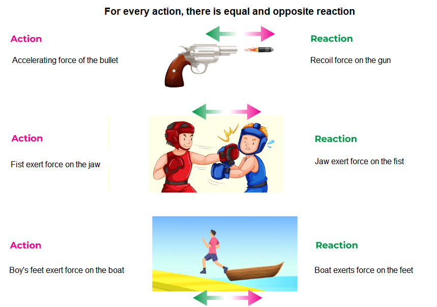
From Newton’s 3rd law, it can be analysed that we cannot produce a single isolated force in nature. Thus, forces occur in equal and opposite pairs. Whenever object \(A\) exerts a force on object \(B\), object \(B\) must also exert a force on object \(A\). The two forces are equal in magnitude and opposite in direction.
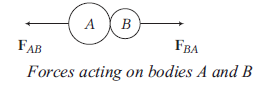
As shown in figure, if \(\mathrm{F}_{B A}\) is the force exerted by body \(A\) on \(B\) and \(\mathbf{F}_{A B}\) is the force exerted by \(B\) on \(A\), then according to Newton’s third law,
\(
\mathrm{F}_{A B}=-\mathrm{F}_{B A}
\)
Force on \(A\) by \(B=-\) Force on \(B\) by \(A\)
Important features of Newton’s 3rd law of motion
- Newton’s third law of motion is applicable irrespective of the nature of the forces: The forces of action and reaction may be mechanical, gravitational, electric or of any other nature.
- Action and reaction always act on two different bodies: If they act on the same body, the resultant force would be zero and there could never be accelerated motion.
- The force of action and reaction cannot cancel each other: This is because action and reaction, though equal and opposite forces always act on different bodies and so cannot cancel each other.
- No action can occur in the absence of a reaction: In a tug of war, one team can pull the rope only if the other team is pulling the other end of the rope; no force can be exerted, if the other end is free. One team exerts the force of action and the other team provides the force of reaction.
Example 1: A block of mass 25 kg is raised by a 50 kg man in two different ways as shown in figure. What is the action on the floor by the man in the two cases? If the floor yields to a normal force of \(700 N\), which mode should the man adopt to lift the block without the floor yielding? (Take, \(g=9.8 \mathrm{~ms}^{-2}\) )
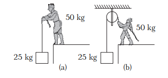
Solution: In mode (a), the man applies a force equal to 25 kg weight in upward direction. According to Newton’s third law of motion, there will be a downward force of reaction on the floor.
\(\therefore\) Total action on the floor by the man
\(
\begin{aligned}
& =50 \mathrm{~kg}-\mathrm{wt}+25 \mathrm{~kg}-\mathrm{wt} \\
& =75 \mathrm{~kg}-\mathrm{wt} \\
& =75 \times 9.8 \mathrm{~N}=735 \mathrm{~N}
\end{aligned}
\)
In mode (b), the man applies a downward force on rope equal to 25 kg -wt. According to Newton’s third law, the reaction will be in the upward direction by the rope on the man, so he becomes light by \(25 \mathrm{~kg}-\mathrm{wt}\).
\(\therefore\) Total action on the floor by the man
\(
\begin{aligned}
& =50 \mathrm{~kg}-\mathrm{wt}-25 \mathrm{~kg}-\mathrm{wt} \\
& =25 \mathrm{~kg}-\mathrm{wt} \\
& =25 \times 9.8 \mathrm{~N}=245 \mathrm{~N}
\end{aligned}
\)
As the floor yields to a downward force of 700 N , so the man should adopt mode (b).
Example 2: A heavy particle of mass 0.50 kg is hanging from a string fixed with the roof. Find the force exerted by the string on the particle (Figure below). Take \(g=9.8 \mathrm{~m} / \mathrm{s}^2\).
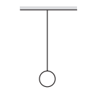
Solution: The forces acting on the particle are
(a) pull of the earth, \(0.50 \mathrm{~kg} \times 9.8 \mathrm{~m} / \mathrm{s}^2=4.9 \mathrm{~N}\), vertically downward
(b) pull of the string, \(T\) vertically upward.
The particle is at rest with respect to the earth (which we assume to be an inertial frame). Hence, the sum of the forces should be zero. Therefore, \(T\) is 4.9 N acting vertically upward.
What Is a Frame of Reference?
We have learned about velocity, acceleration, and displacement. But all these quantities need a frame of reference from which they are measured. In physics, a frame of reference consists of an abstract coordinate system and the set of physical reference points that uniquely fix the coordinate system and standardize measurements within that frame.
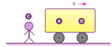
If we ask A what velocity of B is, he will say it is at rest. But if we ask the same question to C, he will say B is moving with a velocity V in the positive X direction. So we can see before specifying the velocity we have to specify in which frame we are or in simple terms, we need to define a frame of reference.
Types of Frame of Reference
Once we have chosen our reference they can be of two types:
- Inertial Frame of Reference
- Non-inertial Frame of Reference
Inertial Frame of Reference
An inertial frame of reference is a frame where Newton’s law holds true. That means if no external force is acting on a body it will stay at rest or remain in uniform motion. Suppose a body is kept on the surface of the earth, for a person on earth it is at rest while for a person on the moon it is in motion so which is my inertial frame here? Actually, the term inertial frame is relative i.e. first we assume a reference frame to be the inertial frame of reference. So a more general definition of an inertial frame would be: Inertial frame is at rest or moves with constant velocity with respect to my assumed inertial reference frame.
A reference frame which is either at rest or in uniform motion along the straight line. A non-accelerating frame of reference is called an inertial frame of reference. All the fundamental laws of physics have been formulated in respect of inertial frame of reference.
Non-inertial Frame of Reference
Now we can define a non-inertial frame as a frame that is accelerated with respect to the assumed inertial frame of reference. Newton’s law will not hold true in these frames. So in the above example if I assume earth to be an inertial reference frame the moon becomes a non-inertial reference frame as it is in accelerated motion with respect to earth. But if we want to make Newton’s law hold here we need to take some mysterious forces also known as pseudo forces.
An accelerating frame of reference is called a non-inertial frame of reference. Newton’s laws of motion are not directly applicable in such frames, before application we must add pseudo force.
Few examples are shown below:
A frame of reference, also referred to as a reference frame, is a conceptual framework used to establish a coordinate system and a set of reference points. Its purpose is to provide a standardized means of measuring and describing the position, velocity, and other characteristics of objects within that frame. By defining a coordinate system and reference points, a frame of reference facilitates the consistent and accurate comparison and analysis of physical phenomena from a particular perspective.
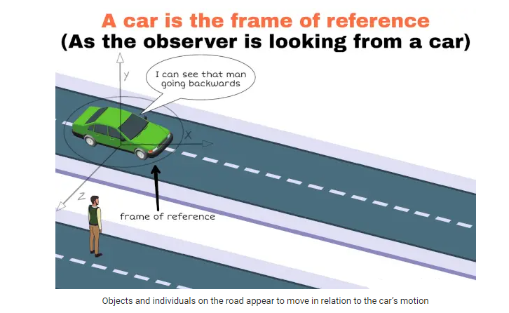
When driving a car, an individual may notice that a pedestrian walking on the road appears to be moving in the opposite direction. This perception is influenced by the frame of reference chosen, which is the car itself. From the perspective of the car, stationary objects and individuals on the road may seem to be in motion relative to the car’s own movement. This observation highlights the importance of considering the frame of reference when interpreting the motion of objects in relation to one’s own position and movement.
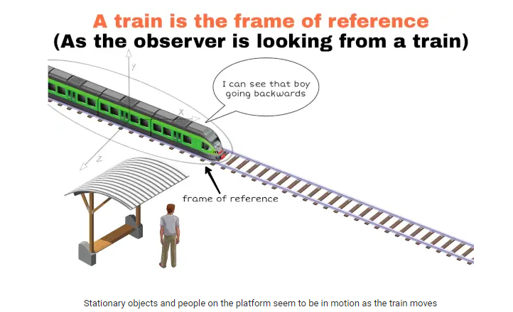
Imagine a train in motion, with an individual seated inside and observing the surroundings. From their vantage point, they will observe that the objects in the surrounding area, as well as the people on the platform, appear to be in motion. This observation is a consequence of the frame of reference they have chosen, which is the moving train itself. As the person inside the train moves along with it, they perceive the stationary objects on the platform as moving relative to their frame of reference.
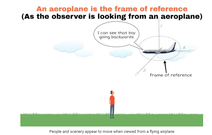
During an airplane takeoff, passengers may notice that the scenery outside seems to quickly move away from them. This happens because their frame of reference is the inside of the moving airplane. As the plane gains speed on the runway and lifts off the ground, the objects on the ground appear to move farther away from their perspective. This perception is a result of the relative motion between the airplane and the stationary objects on the ground, illustrating the influence of the chosen frame of reference on how we perceive motion during an airplane takeoff.
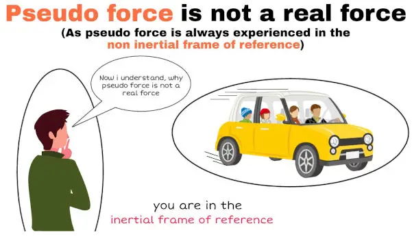
Pseudo Force
Pseudo, the word means false. Therefore, pseudo force is a false or an imaginary force. Pseudo force is a force that does not actually exist, but it appears to be present when the frame of reference is accelerating. It is also known as a fictitious force, inertial force, or d’Alembert force. It means that in the frame of every accelerating body, a pseudo force appears to be acting on all the objects contained in the frame. The direction of the pseudo force is always opposite to the direction of acceleration of the frame. The acceleration with which the objects in the frame appear to be moving is the same as that of the acceleration with which the object moves. The magnitude of the pseudo force is equal to the product of the mass of the object and the acceleration of the frame. The frame that is not accelerating is known as the inertial frame, whereas the frame that is accelerating is known as the non-inertial frame. Few examples are given below:
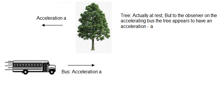
Case-I: Accelerating Bus
Case-II: A person watching a moving car
Case-III: Lift (Accelerating Upward)
When we descend in a lift, a tremendous force pulls our body higher. Due to this illusion force, things outside the moving lift appear to be going at the same rate as the lift but in the opposite direction. The pseudo force, a fictitious force, is the force that causes something to happen. When an elevator is moving with an acceleration, it becomes a non-inertial frame of reference. We find it difficult to apply Newton’s laws of motion for a non-inertial frame of reference when the observer is a part of that reference.
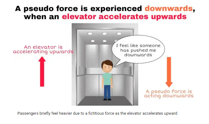
When an elevator accelerates upward, passengers inside may briefly feel a sensation of increased weight. This happens because, from their perspective inside the elevator, it appears as if a fictitious force is acting, making gravity seem stronger. In reality, gravity remains the only real force acting on passengers, constantly pulling them downward. However, when the elevator accelerates upward, passengers find themselves in a reference frame that is also undergoing acceleration. This creates the perception of an additional, or ‘fictitious,’ force pushing them downward, resulting in the feeling of greater weight. This change in apparent weight is due to the elevator’s upward acceleration, which alters how passengers perceive the effects of gravity.
Case-IV: Car speeding up
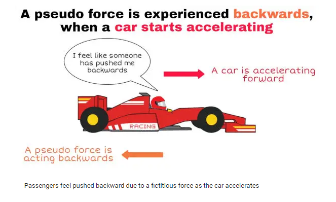
When a car accelerates, an observer inside the vehicle may sense a backward force, as if an invisible hand pushes them into their seat. This sensation results from fictitious force, specifically the ‘inertial’ or ‘pseudo’ force. No external force pushes the passenger; it’s the car’s acceleration itself. According to Newton’s first law of motion, objects stay at rest or move straight unless acted upon by an external force. As the car accelerates, the passenger tends to stay still due to their inertia. The apparent backward force arises as the car ‘drags’ the passenger along. This illustrates how fictitious forces help us understand motion in accelerating frames, despite no real external forces.
Formula
Pseudo force formula: \(F_p=-\) ma
where,
\(F_p=\) pseudo force acting on an object
\(\mathrm{m}\) = mass of an object
\(\mathrm{a}=\) acceleration of an object’s frame of reference
\((-)\) sign indicates that pseudo force is acting in the opposite direction to the acceleration of an object’s frame of reference.
Pseudo Force Calculation with Railroad Cart example-1:
Consider a situation in which one person is standing on a railroad cart and another is standing on the ground near the railway track. When the cart begins to move forward, the observer on the ground notices the vehicle moving but notices no movement in the rocks surrounding him. The guy standing on the railroad cart, on the other hand, perceives the rock on the ground as moving at the same rate as the railroad cart, which seems to be stationary to him. The rocks move backward without applying any force, according to the person standing on the cart. The rocks appear to be shifting due to the cart’s movement. A force seems to be acting on the rocks in the frame, pulling them backward. The pseudo force is the name given to this fake power.
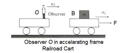
Let us assume that, a block \(B\) is moving on a cart when a constant force \(\vec{F}\) is applied on it, as shown in the figure, \(\vec{a_1}=\vec{F} / m\) is acceleration of the block having mass \(m\).
If this block \((B)\) is observed by an observer \((O)\) standing on frame which is accelerating with acceleration \(\vec{a}_2\), then acceleration of block w.r.t. observer,
\(
\vec{a}_{B / O}=\vec{a}_B-\vec{a}_O=\vec{a_1}-\vec{a}_2
\)
Force on the block as observed by the observer \(\vec{F}_{B / O}=m\left(\vec{a_1}-\vec{a}_2\right)=m \vec{a_1}-m \vec{a_2}\) or \(\vec{F}_{B / O}=\vec{F}+\vec{F}_{\text {pseudo }}\)
So, \(\vec{F}_{\text {pseudo }}=-m \vec{a}_2\)
If an object of mass \(m\) is observed from a non-inertial reference frame having acceleration, then pseudo force will be \(\vec{F}_{\text {pseudo }}=-m \vec{a}_2\)
For non-inertial frame, \(\vec{F}_{\text {ext }}+\vec{F}_{\text {pseudo }}=m \vec{a_1}\), where \(\vec{a_1}\) is the acceleration of the object with respect to the frame and \(F_{\text {ext }}\) is the external force.
Note: When we draw the free body diagram of a mass, with respect to an inertial frame of reference we apply only the real forces (forces which are actually acting on the mass). But when the free body diagram is drawn from a noninertial frame of reference a pseudo force (in addition to all real forces) has to be applied to make the equation \(\overrightarrow{\mathrm{F}}=\mathrm{m} \overrightarrow{\mathrm{a}}\) to be valid in this frame also.
\(\sum \overrightarrow{\mathrm{F}}_{\text {real }}+\overrightarrow{\mathrm{F}}_{\mathrm{pseudo}}=\mathrm{m}\overrightarrow{\mathrm{a}}\) (where \(\overrightarrow{\mathrm{a}}\) is acceleration of object in non inertial reference frame) & \(\overrightarrow{\mathrm{F}}_{\mathrm{pseudo}}=-\mathrm{m} \overrightarrow{\mathrm{a}}_{\mathrm{0}}\) (where \(\overrightarrow{\mathrm{a}}_0\) is acceleration of non inertial reference frame).
Example 3: Two identical billiard balls strike a rigid wall with the same speed but at different angles, and get reflected without any change in speed, as shown in Figure below. What is (i) the direction of the force on the wall due to each ball? (ii) the ratio of the magnitudes of impulses imparted to the balls by the wall?
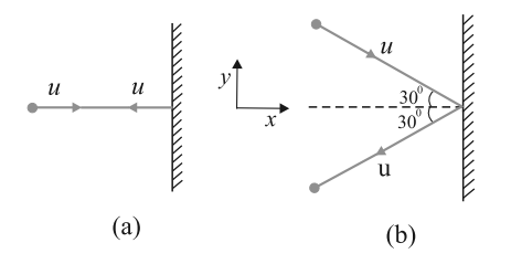
Solution: An instinctive answer to (i) might be that the force on the wall in case (a) is normal to the wall, while that in case (b) is inclined at \(30^{\circ}\) to the normal. This answer is wrong. The force on the wall is normal to the wall in both cases.
How to find the force on the wall? The trick is to consider the force (or impulse) on the ball due to the wall using the second law, and then use the third law to answer (i). Let \(u\) be the speed of each ball before and after collision with the wall, and \(m\) the mass of each ball. Choose the \(x\) and \(y\) axes as shown in the figure, and consider the change in momentum of the ball in each case :
Case (a)
\(
\begin{array}{ll}
\left(p_x\right)_{\text {initial }}=m u & \left(p_y\right)_{\text {intital }}=0 \\
\left(p_x\right)_{\text {tinal }}=-m u & \left(p_y\right)_{\text {traal }}=0
\end{array}
\)
Impulse is the change in momentum vector. Therefore,
\(
\begin{aligned}
& x \text {-component of impulse }=-2 m u \\
& y \text {-component of impulse }=0
\end{aligned}
\)
Impulse and force are in the same direction. Clearly, from above, the force on the ball due to the wall is normal to the wall, along the negative x -direction. Using Newton’s third law of motion, the force on the wall due to the ball is normal to the wall along the positive \(x\)-direction. The magnitude of force cannot be ascertained since the small time taken for the collision has not been specified in the problem.
\(
\begin{aligned}
&\text { Case (b) }\\
&\begin{aligned}
& \left(p_x\right)_{\text {initial }}=m u \cos 30^{\circ},\left(p_y\right)_{\text {initial }}=-m u \sin 30^{\circ} \\
& \left(p_x\right)_{\text {final }}=-m u \cos 30^{\circ},\left(p_y\right)_{\text {final } I}=-m u \sin 30^{\circ}
\end{aligned}
\end{aligned}
\)
Note, while \(p_x\) changes sign after collision, \(p_y\) does not. Therefore,
\(x\)-component of impulse \(=-2 m u \cos 30^{\circ}\)
\(y\)-component of impulse \(=0\)
The direction of impulse (and force) is the same as in (a) and is normal to the wall along the negative \(x\) direction. As before, using Newton’s third law, the force on the wall due to the ball is normal to the wall along the positive \(x\) direction.
The ratio of the magnitudes of the impulses imparted to the balls in (a) and (b) is
\(
2 m u /\left(2 m u \cos 30^{\circ}\right)=\frac{2}{\sqrt{3}} \approx 1.2
\)