6.8 Equilibrium of a rigid body
A rigid body is said to be in mechanical equilibrium, if both its linear momentum and angular momentum are not changing with time. or equivalently, the body has neither linear acceleration nor angular acceleration. This means the total force, i.e. the vector sum of the forces, on the rigid body is zero.
Translational Equilibrium (No linear acceleration):
The vector sum of all external forces acting on the body is zero.
\(
\mathbf{F}_{n e t}=\sum_{i=1}^n \mathbf{F}_i=\mathbf{F}_1+\mathbf{F}_2+\ldots+\mathbf{F}_n=\mathbf{0} \dots(i)
\)
If the total force on the body is zero, then the total linear momentum of the body does not change with time. Eq. (i) gives the condition for the translational equilibrium of the body.
Reasoning: We know \(\mathbf{F}_{n e t}=\frac{d \mathbf{P}}{d t}\) and \(\mathbf{P}=m \mathbf{v}\). If the total external force on a body (or system) is zero, its total linear momentum \(\mathbf{P}\) doesn’t change. If \(\mathbf{F}_{n e t}\) is zero, then \(\frac{d \mathbf{P}}{d t}\) must also be zero, meaning momentum ( \(\mathbf{P}\) ) is constant over time, leading to the Law of Conservation of Momentum.
Rotational Equilibrium (No angular acceleration):
The total torque, i.e. the vector sum of the torques on the rigid body is zero (the vector sum of all external torques (moments) about any point is zero).
\(
\boldsymbol{\tau}_{\text {net }}=\sum_{i=1}^n \boldsymbol{\tau}_i=\boldsymbol{\tau}_1+\boldsymbol{\tau}_2+\ldots+\boldsymbol{\tau}_n=\mathbf{0} \dots(ii)
\)
Reasoning: If the total torque on the rigid body is zero, that is \(\boldsymbol{\tau}_{\text {net }}=\frac{d \mathbf{L}}{d t}=0\), therefore the total angular momentum of the body does not change (\(\mathrm{L}\) must be constant for its derivative to be 0) with time. Eq. (ii) gives the condition for the rotational equilibrium of the body.
Linear Momentum Examples:
Constant Velocity: A car traveling in a straight line at a steady speed has zero net force because the engine force balances friction and air resistance, and gravity balances the normal force. Its momentum remains constant.
Collisions in Space: In an isolated system like a collision between two objects in outer space, the internal forces exchange momentum but the total momentum of the combined system before and after the collision remains the same because there are no significant external forces (like gravity or air resistance).
In 3D Form:
Eqn. (i) is vector equation. They are equivalent to three scalar equations each. Eqn. (i) corresponds to
\(
\sum_{i=1}^n F_{i x}=0, \sum_{i=1}^n F_{i y}=0 \text { and } \sum_{i=1}^n F_{i z}=0
\)
where \(F_{i x}, F_{i y}\) and \(F_{i z}\) are respectively the \(x, y\) and \(\boldsymbol{z}\) components of the forces \({F}_{i}\).
Similarly, Eqn. (ii) is equivalent to three scalar equations
\(
\sum_{i=1}^n \tau_{i x}=0, \sum_{i=1}^n \tau_{i y}=0 \text { and } \sum_{i=1}^n \tau_{i z}=0
\)
where \(\tau_{i x}, \tau_{i y}\) and \(\tau_{i x}\) are respectively the \(x, y\) and \(z\) components of the torque \(\tau_i\).
Angular Momentum Examples:
Figure Skater: A spinning figure skater pulls their arms in, decreasing their moment of inertia. As a result, their angular velocity increases, but their total angular momentum remains constant because the net external torque on them is essentially zero (ignoring minor air resistance).
A Bicycle Wheel/Gyroscope: A spinning bicycle wheel or a gyroscope maintains its orientation in space due to the conservation of angular momentum. The torque from gravity is balanced by the normal force from the support, resulting in zero net external torque around the pivot point.
Key Concepts
- External vs. Internal Forces: Internal forces (like a ball pushing on another ball in a collision) change individual momenta but not the total momentum of the system because they occur in equal and opposite pairs (Newton’s Third Law).
- Closed/Isolated System: A system with zero net external force is called a closed or isolated system, where momentum is conserved.
Difference between Torque and Moment
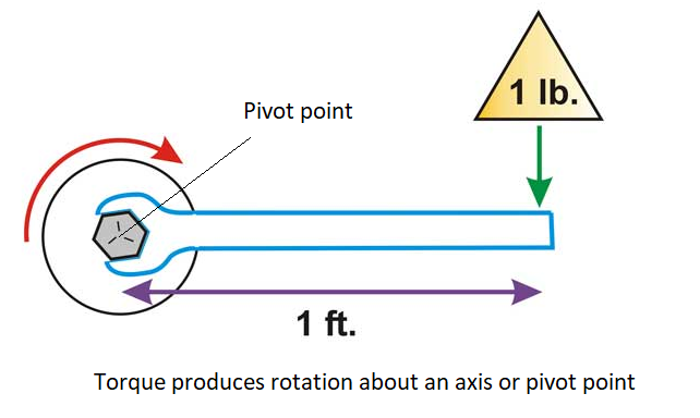
Moment and torque are mathematically similar (Force x Distance) but differ in context: Moment is the general term for a force’s tendency to cause rotation (static bending, tilting), while Torgue specifically refers to a moment causing rotational motion or twisting (dynamic, causing angular acceleration [change in rotational motion]), like turning a wrench or spinning a shaft (dynamic twisting). Torque makes things rotate (causes angular acceleration); a moment might just bend or tilt (a non-rotating force causing a tendency to rotate).
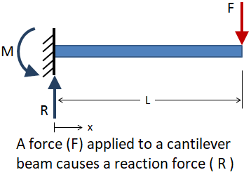
In other words, torque causes a change in the object’s angular momentum, which produces rotation. A moment, on the other hand, does not produce a change in angular momentum. The body to which the moment is applied remains stationary, and reaction forces that arise within the object and its supporting members prevent the object from rotating.
In physics, a pivot point (or fulcrum, axis of rotation) is the fixed point around which an object rotates, experiencing torque.
For example, a load applied to an end-supported cantilever beam will cause a reaction force and a bending moment on the beam, but doesn’t change its angular momentum, and and therefore, doesn’t cause the beam to rotate.
Example 1: Show that moment of a couple does not depend on the point about which you take the moments.
Solution: Define the System: A couple consists of two forces, \(\mathbf{F}\) and \(-\mathbf{F}\), acting at points \(\mathbf{B}\) and \(\mathbf{A}\) respectively, on a rigid body as shown below.
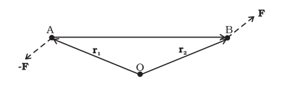
Consider a couple as shown in above figure acting on a rigid body. The forces \(\mathbf{F}\) and \(-\mathbf{F}\) act respectively at points B and A. These points have position vectors \(\mathbf{r}_1\) and \(\mathbf{r}_2\) with respect to origin O (choose an Origin: Pick any arbitrary point O in space as the reference point for calculating moments). Let us take the moments of the forces about the origin.
The moment of the couple = sum of the moments of the two forces making the couple
\(
\begin{aligned}
& =\mathbf{r}_1 \times(-\mathbf{F})+\mathbf{r}_2 \times \mathbf{F} \\
& =\mathbf{r}_2 \times \mathbf{F}-\mathbf{r}_1 \times \mathbf{F} \\
& =\left(\mathbf{r}_2-\mathbf{r}_1\right) \times \mathbf{F}
\end{aligned}
\)
But \(\mathbf{r}_1+\mathbf{A B}=\mathbf{r}_2\), and hence \(\mathbf{A B}=\mathbf{r}_2-\mathbf{r}_1\).
The moment of the couple, therefore, is \(\mathbf{A B} \times \mathbf{F}\).
Clearly this is independent of the origin, the point about which we took the moments of the forces.
Remark
- The formula \(M=F \times d\) is a direct representation of this physical principle: the turning power (moment) is the product of the force’s strength and its effective perpendicular distance from the pivot point. The Simplest Case ( \(d \perp {F}\) ): When the force is applied perpendicularly (e.g., \(\theta=90^{\circ}, \sin \left(90^{\circ}\right)=1\) ), the formula simplifies to:\(F \times d \).
- Moment (or torque) is \(F \times d\) because it quantifies the turning effect (rotation) a force creates around a pivot, and this effect is strongest when the force is strong (\(F\)) and applied far from the pivot (the perpendicular distance, \({d}\) ), making it the direct product of these two factors, much like opening a door is easier further from the hinges. The formula captures that a greater perpendicular push or a longer lever arm yields more rotational power.
Example 2: Show with examples a body may be in partial equilibrium, i.e., it may be in translational equilibrium and not in rotational equilibrium, or it may be in rotational equilibrium and not in translational equilibrium.
Solution: Consider a light (i.e. of negligible mass) rod \((\mathrm{AB})\), at the two ends ( \(A\) and \(B\) ) of which two parallel forces both equal in magnitude are applied perpendicular to the rod as shown in Figure(a).
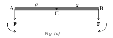
Let \(C\) be the midpoint of \(\mathrm{AB}, \mathrm{CA}=\mathrm{CB}=a\). the moment of the forces at \(A\) and \(B\) will both be equal in magnitude ( \(a F\) ), but opposite in sense as shown. The net moment on the rod will be zero. The system will be in rotational equilibrium, but it will not be in translational equilibrium; \(\sum \mathbf{F} \neq \mathbf{0}\)
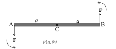
The force at \(B\) in Figure(a) is reversed in Figure(b). Thus, we have the same rod with two equal and opposite forces applied perpendicular to the rod, one at end \(A\) and the other at end \(B\). Here the moments of both the forces are equal, but they are not opposite; they act in the same sense and cause anticlockwise rotation of the rod. The total force on the body is zero; so the body is in translational equilibrium; but it is not in rotational equilibrium. Although the rod is not fixed in any way, it undergoes pure rotation (i.e. rotation without translation).
Principle of moments
An ideal lever is essentially a light (i.e. of negligible mass) rod pivoted at a point (point O) along its length. This point is called the fulcrum. A seesaw on the children’s playground is a typical example of a lever. Two forces \(F_1\) and \(F_2\), parallel to each other and usually perpendicular to the lever, as shown here, act on the lever at distances \(d_1\) and \(d_2\) respectively from the fulcrum as shown in Figure below.
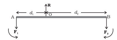
The lever is a system in mechanical equilibrium. Let \(\mathbf{R}\) be the reaction of the support at the fulcrum; \(\mathbf{R}\) is directed opposite to the forces \(F_1\) and \(F_2\). For translational equilibrium (net force is 0),
\(
R-F_1-F_2=0 \dots(i)
\)
For considering rotational equilibrium we take the moments about the fulcrum; the sum of moments must be zero,
\(
d_1 F_1-d_2 F_2=0 \dots(ii)
\)
Normally the anticlockwise (clockwise) moments are taken to be positive (negative). Note \(R\) acts at the fulcrum itself and has zero moment about the fulcrum.
In the case of the lever force \(F_1\) is usually some weight to be lifted. It is called the load and its distance from the fulcrum \(d_1\) is called the load arm. Force \(F_2\) is the effort applied to lift the load; distance \(d_2\) of the effort from the fulcrum is the effort arm.
Eq. (ii) can be written as
\(
d_1 F_1=\mathrm{d}_2 F_2 \dots(iii)
\)
or load arm × load \(=\) effort arm × effort
The above equation expresses the principle of moments for a lever. Incidentally the ratio \(F_1 / F_2\) is called the Mechanical Advantage (M.A.);
\(
\text { M.A. }=\frac{F_1}{F_2}=\frac{d_2}{d_1} \dots(iv)
\)
If the effort arm \(d_2\) is larger than the load arm, the mechanical advantage is greater than one. Mechanical advantage greater than one means that a small effort can be used to lift a large load.
Centre of gravity
The center of gravity (COG) is the average location of an object’s weight, the single point where it can be perfectly balanced, acting as its balance point, and is crucial for understanding stability in physics, engineering (like buildings), and even human posture (as shown below).
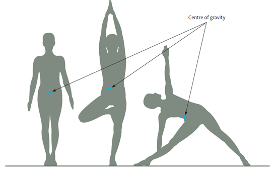
The position of an object’s COG depends upon its shape and how it’s moving. For example, in stationary, standing humans our COG is located deep inside the abdomen. However, when we change our position our COG also changes (see diagram above). Sometimes it’s even located outside of the body.
Illustration-1:
Take an irregular shaped cardboard having mass \(M\) and a narrow tipped object like a pencil. You can locate by trial and error a point G on the cardboard where it can be balanced on the tip of the pencil. (The cardboard remains horizontal in this position.) This point of balance is the centre of gravity (COG) of the cardboard. The tip of the pencil provides a vertically upward force due to which the cardboard is in mechanical equilibrium. As shown in the Figure below, the reaction of the tip is equal and opposite to \(M \mathbf{g}\) and hence the cardboard is in translational equilibrium. It is also in rotational equilibrium; if it were not so, due to the unbalanced torque it would tilt and fall. There are torques on the card board due to the forces of gravity like \(m_1 \mathbf{g}, m_2 \mathbf{g} \ldots\). etc, acting on the individual particles that make up the cardboard.
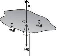
The COG of the cardboard is so located that the total torque on it due to the forces \(m_1 \mathbf{g}, m_2 \mathbf{g}\) …. etc. is zero.
If \(\mathbf{r}_i\) is the position vector of the \(i\) th particle of an extended body with respect to its COG, then the torque about the CG, due to the force of gravity on the particle is \(\boldsymbol{\tau}_i=\mathbf{r}_i \times m_i \mathbf{g}\). The total gravitational torque about the COG is zero, i.e.
\(
\boldsymbol{\tau}_g=\sum \boldsymbol{\tau}_i=\sum \mathbf{r}_i \times m_i \mathbf{g}=\mathbf{0} \dots(1)
\)
We may therefore, define the CG of a body as that point where the total gravitational torque on the body is zero.
We notice that in Eqn. (1), \(\mathbf{g}\) is the same for all particles, and hence it comes out of the summation. This gives, since \(\mathbf{g}\) is non-zero, \(\sum m_i \mathbf{r}_i=\mathbf{0}\). Remember that the position vectors (\(\mathbf{r}\)) are taken with respect to the COG.
Remark:
If the sum is zero (\(\sum m_i \mathbf{r}_i=\mathbf{0}\)), the origin must be the centre of mass of the body. Thus, the centre of gravity of the body coincides with the centre of mass in uniform gravity or gravity-free space. We note that this is true because the body being small, g does not vary from one point of the body to the other. If the body is so extended that \(\mathbf{g}\) varies from part to part of the body, then the centre of gravity and centre of mass will not coincide. Basically, the two are different concepts. The centre of mass has nothing to do with gravity. It depends only on the distribution of mass of the body.
Illustration-2:
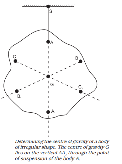
Figure above illustrates another way of determining the COG of an irregular shaped body like a cardboard. If you suspend the body from some point like A, the vertical line through A passes through the COG. We mark the vertical \(\mathrm{AA}_1\). We then suspend the body through other points like B and C. The intersection of the verticals gives the COG. Explain why the method works. Since the body is small enough, the method allows us to determine also its centre of mass.
Example 3: A metal bar 70 cm long and 4.00 kg in mass supported on two knife-edges placed 10 cm from each end. A 6.00 kg weight is suspended at 30 cm from one end. Find the reactions at the knife-edges. (Assume the bar to be of uniform cross section and homogeneous.)
Solution: Figure below shows the rod AB, the positions of the knife edges \(\mathrm{K}_1\) and \(\mathrm{K}_2\), the centre of gravity of the rod at G and the suspended weight at P.
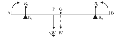
Note that the weight of the rod W acts at its centre of gravity G. The rod is uniform in cross section and homogeneous; hence G is at the centre of the rod; \(\mathrm{AB}=70 \mathrm{~cm}, \mathrm{AG}=35 \mathrm{~cm}, \mathrm{AP} =30 \mathrm{~cm}, \mathrm{PG}=5 \mathrm{~cm}, \mathrm{AK}_1=\mathrm{BK}_2=10 \mathrm{~cm}\) and \(\mathrm{K}_1 \mathrm{G} =\mathrm{K}_2 \mathrm{G}=25 \mathrm{~cm}\). Also, \(W=\) weight of the \(\mathrm{rod}=\) 4.00 kg and \(W_1=\) suspended weight \(=6.00 \mathrm{~kg}\); \(R_1\) and \(R_2\) are the normal reactions of the support at the knife edges.
For translational equilibrium of the rod,
\(
R_1+R_2-W_1-W=0 \dots(i)
\)
Note \(W_1\) and \(W\) act vertically down and \(\mathrm{R}_1\) and \(\mathrm{R}_2\) act vertically up.
For considering rotational equilibrium, we take moments of the forces. A convenient point to take moments about is G. The moments of \(R_2\) and \(W_1\) are anticlockwise (+ve), whereas the moment of \(R_1\) is clockwise (-ve).
For rotational equilibrium.
\(
-R_1\left(\mathrm{~K}_1 \mathrm{G}\right)+W_1(\mathrm{PG})+R_2\left(\mathrm{~K}_2 \mathrm{G}\right)=0 \dots(ii)
\)
It is given that \(W=4.00 \mathrm{~g} \mathrm{~N}\) and \(W_1=6.00 \mathrm{~g}\) N, where \(g=\) acceleration due to gravity. We take \(g=9.8 \mathrm{~m} / \mathrm{s}^2\).
With numerical values inserted, from (i)
\(
\begin{aligned}
& R_1+R_2-4.00 \mathrm{~g}-6.00 \mathrm{~g}=0 \\
& \text { or } R_1+R_2=10.00 \mathrm{~g} \mathrm{~N} \dots(iii) \\
& =98.00 \mathrm{~N}
\end{aligned}
\)
From (ii) \(-0.25 R_1+0.05 W_1+0.25 R_2=0\)
or \(R_2-R_1=1.2 \mathrm{~g} \mathrm{~N}=11.76 \mathrm{~N} \dots(iv)\)
From (iii) and (iv), \(R_1=54.88 \mathrm{~N}\),
\(
R_2=43.12 \mathrm{~N}
\)
Thus the reactions of the support are about 55 N at \(\mathrm{K}_1\) and 43 N at \(\mathrm{K}_2\).
Example 4: A 3 m long ladder weighing 20 kg leans on a frictionless wall. Its feet rest on the floor 1 m from the wall as shown in Figure below. Find the reaction forces of the wall and the floor.
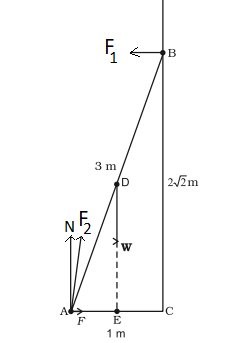
Solution: The ladder AB is 3 m long, its foot A is at distance \(\mathrm{AC}=1 \mathrm{~m}\) from the wall. From Pythagoras theorem, \(\mathrm{BC}=2 \sqrt{2} \mathrm{~m}\). The forces on the ladder are its weight W acting at its centre of gravity D, reaction forces \(F_1\) and \(F_2\) of the wall and the floor respectively. Force \(F_1\) is perpendicular to the wall, since the wall is frictionless. Force \(F_2\) is resolved into two components, the normal reaction \(N\) and the force of friction \(F\). Note that \(F\) prevents the ladder from sliding away from the wall and is therefore directed toward the wall.
For translational equilibrium, taking the forces in the vertical direction,
\(
N-W=0 \dots(i)
\)
Taking the forces in the horizontal direction,
\(
F-F_1=0 \dots(ii)
\)
For rotational equilibrium, taking the moments of the forces about A ,
\(
2 \sqrt{2} F_1-(1 / 2) W=0 \dots(iii)
\)
Now \(W=20 \mathrm{~g}=20 \quad 9.8 \mathrm{~N}=196.0 \mathrm{~N}\)
From (i) \(N=196.0 \mathrm{~N}\)
From (iii) \(F_1=W / 4 \sqrt{2}=196.0 / 4 \sqrt{2}=34.6 \mathrm{~N}\)
From (ii)
\(
\begin{aligned}
F & =F_1=34.6 \mathrm{~N} \\
F_2 & =\sqrt{F^2+N^2}=199.0 \mathrm{~N}
\end{aligned}
\)
The force \(F_2\) makes an angle \(\alpha\) with the horizontal,
\(
\tan \alpha=N / F=4 \sqrt{2}, \quad \alpha=\tan ^{-1}(4 \sqrt{2}) \approx 80^{\circ}
\)