Conceptual PCQs
SUMMARY
- Ideally, a rigid body is one for which the distances between different particles of the body do not change, even though there are forces on them.
- A rigid body fixed at one point or along a line can have only rotational motion. A rigid body not fixed in some way can have either pure translational motion or a combination of translational and rotational motions.
- In rotation about a fixed axis, every particle of the rigid body moves in a circle which lies in a plane perpendicular to the axis and has its centre on the axis. Every Point in the rotating rigid body has the same angular velocity at any instant of time.
- In pure translation, every particle of the body moves with the same velocity at any instant of time.
- Angular velocity is a vector. Its magnitude is \(\omega=d \theta / d t\) and it is directed along the axis of rotation. For rotation about a fixed axis, this vector \(\omega\) has a fixed direction.
- The vector or cross product of two vector \(a\) and \(b\) is a vector written as \(a \times b\). The magnitude of this vector is \(a b \sin \theta\) and its direction is given by the right handed screw or the right hand rule.
- The linear velocity of a particle of a rigid body rotating about a fixed axis is given by \(v = \omega \times r\), where \(r\) is the position vector of the particle with respect to an origin along the fixed axis. The relation applies even to more general rotation of a rigid body with one point fixed. In that case \(r\) is the position vector of the particle with respect to the fixed point taken as the origin.
- The centre of mass of a system of \(n\) particles is defined as the point whose position vector is
\(
R =\frac{\sum m_i r _i}{M}
\) - Velocity of the centre of mass of a system of particles is given by \(V = P / M\), where \(P\) is the linear momentum of the system. The centre of mass moves as if all the mass of the system is concentrated at this point and all the external forces act at it. If the total external force on the system is zero, then the total linear momentum of the system is constant.
- The angular momentum of a system of \(n\) particles about the origin is
\(
L =\sum_{i=1}^n r _i \times p _i
\)
The torque or moment of force on a system of \(n\) particles about the origin is
\(
\tau =\sum_{i=1}^n r _i \times F _i
\)
The force \(F _i\) acting on the \(i^{\text {th }}\) particle includes the external as well as internal forces. Assuming Newton’s third law of motion and that forces between any two particles act along the line joining the particles, we can show \(\tau _{\text {int }}= 0\) and
\(
\frac{d L }{d t}= \tau _{e x t}
\) - A rigid body is in mechanical equilibrium if
(a) it is in translational equilibrium, i.e., the total external force on it is zero : \(\sum F _i= 0\), and
(b) it is in rotational equilibrium, i.e. the total external torque on it is zero :
\(
\sum \tau _i=\sum r _i \times F _i= 0
\) - The centre of gravity of an extended body is that point where the total gravitational torque on the body is zero.
- The moment of intertia of a rigid body about an axis is defined by the formula \(I=\sum m_i r_i^2\) where \(r_i\) is the perpendicular distance of the \(i\) th point of the body from the axis. The kinetic energy of rotation is \(K=\frac{1}{2} I \omega^2\).
- The theorem of parallel axes: \(I_z^{\prime}=I_z+M a^2\), allows us to determine the moment of intertia of a rigid body about an axis as the sum of the moment of inertia of the body about a parallel axis through its centre of mass and the product of mass and square of the perpendicular distance between these two axes.
- Rotation about a fixed axis is directly analogous to linear motion in respect of kinematics and dynamics.
- For a rigid body rotating about a fixed axis (say, \(z\)-axis) of rotation, \(L_{ z }=I \omega\), where \(I\) is the moment of inertia about \(z\)-axis. In general, the angular momentum \(L\) for such a body is not along the axis of rotation. Only if the body is symmetric about the axis of rotation, \(L\) is along the axis of rotation. In that case, \(| L |=L_z=I \omega\). The angular acceleration of a rigid body rotating about a fixed axis is given by \(I \alpha=\tau\). If the external torque \(\tau\) acting on the body is zero, the component of angular momentum about the fixed axis (say, \(z\)-axis), \(L_z(=I \omega)\) of such a rotating body is constant.
- For rolling motion without slipping \(v_{c m}=R \omega\), where \(v_{c m}\) is the velocity of translation (i.e. of the centre of mass), \(R\) is the radius and \(m\) is the mass of the body. The kinetic energy of such a rolling body is the sum of kinetic energies of translation and rotation:
\(
K=\frac{1}{2} m v_{c m}^2+\frac{1}{2} I \omega^2
\)
Quiz Summary
0 of 67 Questions completed
Questions:
Information
You have already completed the quiz before. Hence you can not start it again.
Quiz is loading…
You must sign in or sign up to start the quiz.
You must first complete the following:
Results
Results
0 of 67 Questions answered correctly
Your time:
Time has elapsed
You have reached 0 of 0 point(s), (0)
Earned Point(s): 0 of 0, (0)
0 Essay(s) Pending (Possible Point(s): 0)
Categories
- Not categorized 0%
- 1
- 2
- 3
- 4
- 5
- 6
- 7
- 8
- 9
- 10
- 11
- 12
- 13
- 14
- 15
- 16
- 17
- 18
- 19
- 20
- 21
- 22
- 23
- 24
- 25
- 26
- 27
- 28
- 29
- 30
- 31
- 32
- 33
- 34
- 35
- 36
- 37
- 38
- 39
- 40
- 41
- 42
- 43
- 44
- 45
- 46
- 47
- 48
- 49
- 50
- 51
- 52
- 53
- 54
- 55
- 56
- 57
- 58
- 59
- 60
- 61
- 62
- 63
- 64
- 65
- 66
- 67
- Current
- Review
- Answered
- Correct
- Incorrect
- Question 1 of 67
1. Question
Consider the following two equations:
(A) \(\quad \vec{R}=\frac{1}{M} \sum_i m_i \vec{r}_i\)
and
(B) \(\vec{a}_{C M}=\frac{\vec{F}}{M}\).
In a noninertial frameCorrectIncorrectHint
(c) (A) is a definition of the center-of-mass position. It depends only on how positions are measured in the chosen frame.
If you change to a non-inertial frame, all the \(\vec{r}_i\) change in the same way, and the definition still holds (so does not depend of frame of reference).
So (A) is true in any reference frame.
However, the equation for the acceleration of the center of mass (B) is based on Newton’s second law, which is only valid in inertial frames. In a noninertial frame, pseudo-forces must be considered. - Question 2 of 67
2. Question
Consider the following two statements :
(A) Linear momentum of the system remains constant.
(B) Centre of mass of the system remains at rest.CorrectIncorrectHint
(d) Statement (A)
Linear momentum of the system remains constant
This means:
\(
\vec{P}=\text { constant }
\)
But the constant need not be zero.
So the centre of mass can move with constant velocity:
\(
\vec{v}_{C M}=\frac{\vec{P}}{M} \neq 0
\)
Hence, (A) does not imply (B).
Statement (B)
Centre of mass of the system remains at rest
This means:
\(
\vec{v}_{C M}=0
\)
So, \(\vec{P}=M \vec{v}_{C M}=0\)
Zero momentum is certainly constant, therefore (B) implies (A). - Question 3 of 67
3. Question
Consider the following two statements :
(A) Linear momentum of a system of particles is zero.
(B) Kinetic energy of a system of particles is zero.CorrectIncorrectHint
(d) If the linear momentum of a system is zero,
\(
\Rightarrow m_1 \vec{v}_1+m_2 \vec{v}_2+\ldots=0
\)
Thus, for a system of comprising two particles of same masses,
\(
\vec{v}_1=-\vec{v}_2 \dots(1)
\)
The kinetic energy of the system is given by,
\(
K . E .=\frac{1}{2} m \vec{v}_1^2+\frac{1}{2} m \vec{v}_2^2
\)
Using equation (1) to solve above equation, we can say:
K.E. \(\neq 0\)
i.e A does not imply B.
Now, If the kinetic energy of the system is zero,
\(
\begin{aligned}
& \Rightarrow \frac{1}{2} m \vec{v}_1^2+\frac{1}{2} m \vec{v}_2^2=0 \\
& v_1= \pm v_2
\end{aligned}
\)
On calculating the linear momentum of the system, we get:
\(
\vec{P}=m \vec{v}_1+m \vec{v}_2 \quad \text { Taking } v_1= – v_2
\)
\(
\vec{P}=0
\)
Hence, we can say, B implies A but A does not imply B. - Question 4 of 67
4. Question
Consider the following two statements:
(A) The linear momentum of a particle is independent of the frame of reference.
(B) The kinetic energy of a particle is independent of the frame of reference.CorrectIncorrectHint
(d) As the velocity of the particle depends on the frame of reference, the linear momentum as well as the kinetic energy is dependent on the frame of reference.
Explanation:
Linear Momentum: \(p=m v\),
r momentum is directly proportional to velocity. If you are standing on a train platform and see a 1-kg ball moving at \(10 \mathrm{~m} / \mathrm{s}\), you calculate its momentum as \(10 \mathrm{~kg} \cdot \mathrm{~m} / \mathrm{s}\). However, if you are running alongside the ball at the same speed, its velocity relative to you is zero, and therefore its momentum in your frame is \(0 \mathrm{~kg} \cdot \mathrm{~m} / \mathrm{s}\).Kinetic Energy: \(K=\frac{1}{2} m v^2\)
Kinetic energy is even more sensitive to the frame of reference because it depends on the square of the velocity.
Zero-KE Frame: If an observer moves at the same velocity as an object, the object appears at rest \((v=0)\), meaning it has zero kinetic energy in that frame.
The Center-of-Momentum (COM) Frame: For a system of multiple particles, the COM frame is the unique inertial frame where the total momentum is zero. This frame provides the minimum possible value for the total kinetic energy of that system. - Question 5 of 67
5. Question
All the particles of a body are situated at a distance \(R\) from the origin. The distance of the centre of mass of the body from the origin is
CorrectIncorrectHint
(b) Reasoning:
The center of mass is a “weighted average” of the positions of all the particles in a body. If every single particle is located at exactly the same distance \(R\) from the origin, they all lie on the surface of a sphere (or the perimeter of a circle in 2D) with radius \(R\).
Case 1: Equal to \(R(\mathrm{COM}=R)\) If all the particles are concentrated at a single point, then the center of mass is at that exact point, which is distance \(R\) from the origin.
Case 2: Less than \(R(\mathrm{COM}<R)\) If the particles are distributed around the sphere (for example, two particles on opposite sides), the center of mass will fall inside the sphere, closer to the origin than the particles themselves.Mathematical Proof
The position vector of the center of mass \(R_{c m}\) for a system of \(n\) particles is given by:
\(
R_{c m}=\frac{\sum m_i r_i}{\sum m_i}
\)
By the Triangle Inequality (the magnitude of a sum is less than or equal to the sum of the magnitudes):
\(
\left|R_{c m}\right|=\frac{\left|\sum m_i r_i\right|}{M} \leq \frac{\sum\left|m_i r_i\right|}{M}
\)
Since the distance of every particle is \(\left|r_i\right|=R\) :
\(
\left|R_{c m}\right| \leq \frac{\sum m_i R}{M}=\frac{R \sum m_i}{M}=\frac{R \cdot M}{M}=R
\)
Summary:
The center of mass cannot be further than \(R\) because it must stay within the “convex hull” of the particles.
It is equal to \(R\) only if all particles are at the same spot.
It is less than \(R\) if the particles are spread out. - Question 6 of 67
6. Question
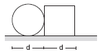
A circular plate of diameter \(d\) is kept in contact with a square plate of edge \(d\) as shown in figure below. The density of the material and the thickness are same everywhere. The centre of mass of the composite system will be
 CorrectIncorrect
Hint
(b) inside the square plate.
This is a classic problem from physics. To solve it, we compare the mass of the two objects and see which “side” pulls the center of mass (COM) toward itself.
Step 1: Mass Comparison:
Since the density ( \(\rho\) ) and thickness ( \(t\) ) are the same for both plates, their masses are directly proportional to their areas \((A)\).
Area of Square \(\left(A_{s q}\right): d^2\)
Area of Circle \(\left(A_{\text {circ }}\right): \frac{\pi d^2}{4} \approx 0.785 d^2\)
Comparing the two:
\(
A_{s q}>A_{\text {circ }} \Longrightarrow \text { Mass of Square }>\text { Mass of Circle }
\)
Step 2: Locating the Center of Mass:
The center of mass of a composite system always lies on the line joining the individual centers of mass of the components.
The COM of the circular plate is at its geometric center.
The COM of the square plate is at its geometric center.
The “balance point” (system COM) will be shifted toward the heavier object. Since the square plate has more mass than the circular plate, the system’s center of mass must be closer to the center of the square than to the center of the circle.
Step 3:Verification by Coordinates
Let the point of contact be the origin \((0,0)\).
Circle COM: \(x_1=-\frac{d}{2}\)
Square COM: \(x_2=+\frac{d}{2}\)
The \(x\)-coordinate of the system COM is:
\(
X_{c m}=\frac{m_{c i r c} x_1+m_{s q} x_2}{m_{c i r c}+m_{s q}}
\)
Because \(m_{s q}>m_{\text {circ }}\), the positive term ( \(m_{s q} \cdot \frac{d}{2}\) ) will outweigh the negative term ( \(m_{\text {circ }} \cdot-\frac{d}{2}\) ), making \(X_{c m}\) positive. Since any positive \(x\) value in this setup puts the point inside the square plate, the COM lies within the square. - Question 7 of 67
7. Question
Consider a system of two identical particles. One of the particles is at rest and the other has an acceleration \(\vec{a}\). The centre of mass has an acceleration
CorrectIncorrectHint
(b) The Formula:
The acceleration of the center of mass ( \(a_{c m}\) ) is the mass-weighted average of the accelerations of the individual particles:
\(
a_{c m}=\frac{m_1 a_1+m_2 a_2}{m_1+m_2}
\)
Step-by-Step Calculation
Based on the problem description, we have two identical particles:
Masses: Since the particles are identical, \(m_1=m_2=m\).
Acceleration of Particle 1: The particle is at rest, so its acceleration is \(a_1=0\).
Acceleration of Particle 2: The second particle has acceleration \(a_2=a\).
Now, substitute these values into the formula:
\(
\begin{gathered}
a_{c m}=\frac{m(0)+m(a)}{m+m} \\
a_{c m}=\frac{m a}{2 m} \\
a_{c m}=\frac{1}{2} a
\end{gathered}
\) - Question 8 of 67
8. Question
Internal forces can change
CorrectIncorrectHint
(b) the kinetic energy but not the linear momentum.
Internal forces are the forces that particles within a system exert on each other. Their effect on the system’s overall motion and energy can be broken down as follows:
Why Linear Momentum remains Constant:
According to Newton’s Third Law, internal forces always occur in equal and opposite pairs. For every internal force \(F_{12}\) (the force exerted by particle 1 on particle 2), there is a corresponding force \(F_{21}\) (the force exerted by particle 2 on particle 1 ) such that:
\(
F_{12}=-F_{21}
\)
When we calculate the total force on the system, these pairs cancel out:
\(
\sum F_{\text {internal }}=F_{12}+F_{21}=0
\)
Since the net force determines the rate of change of linear momentum ( \(F_{\text {net }}=\frac{d p}{d t}\) ), a zero net internal force means that internal forces cannot change the total linear momentum of the system.
Why Kinetic Energy can Change:
While internal forces cancel out in terms of force, they do not necessarily cancel out in terms of work done. Kinetic energy changes based on the net work done on the particles ( \(W=\Delta K\) ).
If the internal forces cause particles to move closer together or further apart, they can perform work, which converts potential energy or internal chemical energy into kinetic energy (or vice versa).Common Examples:
An Explosion: A bomb at rest has zero linear momentum and zero kinetic energy. When it explodes due to internal chemical forces, the fragments fly in all directions. The total momentum remains zero (the vectors cancel out), but the total kinetic energy increases significantly. - Question 9 of 67
9. Question
A bullet hits a block kept at rest on a smooth horizontal surface and gets embedded into it. Which of the following does not change?
CorrectIncorrectHint
(c) gravitational potential energy of the block.
In this scenario (a perfectly inelastic collision), several physical changes occur simultaneously. Here is the breakdown of why the other options change while the potential energy remains constant.
Why Gravitational Potential Energy (GPE) does not change:The block is resting on a horizontal surface. Since the bullet moves horizontally and gets embedded, the block moves along the surface but does not move vertically.
The formula for GPE is \(U=m g h\).
Since the height (h) of the block’s center of mass relative to the ground does not change, the gravitational potential energy remains constant.
Why the other options change:a) Linear Momentum: Initially, the block is at rest ( \(p=0\) ). After the bullet hits it, the block starts moving to conserve the momentum of the bullet-block system. Therefore, the block’s momentum increases.
b) Kinetic Energy: Since the block goes from being stationary \((v=0)[latex] to having a final velocity, its kinetic energy [latex]\left(\frac{1}{2} m v^2\right)\) must increase.
(d) Temperature: In an inelastic collision where a bullet gets embedded, a significant amount of the system’s initial kinetic energy is lost. This “lost” energy is converted into internal energy (heat and deformation), which causes the temperature of both the bullet and the block to rise. - Question 10 of 67
10. Question
A uniform sphere is placed on a smooth horizontal surface and a horizontal force \(F\) is applied on it at a distance \(h\) above the surface. The acceleration of the centre
CorrectIncorrectHint
(d) is independent of \(h\).
To understand why, we need to separate the translational motion (linear acceleration) from the rotational motion (torque and angular acceleration).
Translational Motion:
According to Newton’s Second Law for a system of particles (or a rigid body), the acceleration of the center of mass ( \(a_{c m}\) ) is determined solely by the net external force acting on the body:
\(
F_{n e t}=M a_{c m}
\)
In this problem:
The surface is smooth, meaning there is no friction.
The only horizontal force acting on the sphere is \(F\).
Since \(F\) is the only horizontal force, the equation becomes \(F=M a_{c m}\), which rearranges to:
\(
a_{c m}=\frac{F}{M}
\)
Which is independent of \(h\).
Why the height \(h\) doesn’t matter for \(a_{c m}\):
The point of application of the force affects the torque \((\tau)[latex], which in turn affects how fast the sphere rotates [latex](\alpha)\).
If \(h=R\) (force applied at the center), the torque is zero. The sphere translates without rotating.
If \(h \neq R\), the force creates a torque \(\tau=F(h-R)\), causing the sphere to rotate while it moves.
However, the linear acceleration of the center of mass does not “care” where the force is applied, as long as the force vector itself is the same. Whether you push the sphere at the bottom, the middle, or the top, the center of mass will accelerate at the exact same rate of \(\)F / M\(\). - Question 11 of 67
11. Question
A body falling vertically downwards under gravity breaks in two parts of unequal masses. The centre of mass of the two parts taken together shifts horizontally towards
CorrectIncorrectHint
(c) does not shift horizontally.
This is a fundamental application of the principle of Center of Mass (COM) motion and
Newton’s Laws.The Physics Behind It
The motion of the center of mass of a system is determined only by external forces acting on that system.
Identify External Forces: Before and after the body breaks, the only external force acting on the system is gravity ( \(M g[latex] ). Gravity acts strictly in the vertical direction.
Horizontal External Force: Since there are no external forces acting in the horizontal direction ( [latex]\sum F_x=0\) ), the horizontal acceleration of the center of mass ( \(a_{c m, x}\) ) must be zero.
Initial Horizontal Velocity: The body was falling “vertically downwards,” meaning its initial horizontal velocity ( \(v_{c m, x}\) ) was zero.
Conclusion:
Because the horizontal acceleration is zero and the initial horizontal velocity was zero, the center of mass cannot move horizontally.Even though the two individual pieces might fly apart horizontally due to internal forces (like an internal explosion or structural failure), they must do so in a way that their mass-weighted positions always “balance out” to keep the center of mass on the original vertical path.
- Question 12 of 67
12. Question
A ball kept in a closed box moves in the box making collisions with the walls. The box is kept on a smooth surface. The velocity of the centre of mass
CorrectIncorrectHint
(b) of the box plus the ball system remains constant.
This problem is a classic application of the Conservation of Linear Momentum and the concept of Internal Forces.
The Box-plus-Ball System:
When we consider the ball and the box together as a single system:
The collisions between the ball and the walls of the box are internal forces.
According to Newton’s Third Law, these forces are equal and opposite, so they cancel out and cannot change the total momentum of the system.
The surface is smooth, meaning there is no external horizontal friction.
Since the net external horizontal force ( \(\sum F_{\text {ext }}\) ) is zero, the acceleration of the center of mass ( \(a_{c m}\) ) of the system is zero.Therefore, the velocity of the center of mass of the system remains constant.
Why the other options are incorrect:
(a) The Box: When the ball hits a wall, it exerts an impulsive force on the box. This causes the box to jerk or change its velocity. Thus, the box’s velocity is not constant.
(c) The Ball: Every time the ball hits a wall, its direction (and thus its velocity) changes.
(d) Relative Velocity: The ball’s velocity relative to the box changes every time a collision occurs (e.g., it goes from moving \(+v\) relative to the box to \(-v\) after hitting the right wall).Summary of Motion:
If the box was initially at rest, the ball and the box will move back and forth in such a way that the “balance point” (the center of mass) of the entire system stays exactly where it was. - Question 13 of 67
13. Question
A body at rest breaks into two pieces of equal masses. The parts will move
CorrectIncorrectHint
(c) in opposite directions with equal speeds.
This scenario is a direct application of the Law of Conservation of Linear Momentum.
The Physics Breakdown:
Initial Momentum ( \(P_i\) ): The body is initially at rest, so its initial velocity is zero.
\(
P_i=M \cdot 0=0
[latex]
Internal Forces: The breaking of the body is caused by internal forces. As we discussed earlier, internal forces cannot change the total momentum of a system. Therefore, the final total momentum ( [latex]P_f\) ) must also be zero.
Final Momentum ( \(P_f\) ): Let the two pieces have masses \(m_1[latex] and [latex]m_2\), and velocities \(v_1\) and \(v_2\).
\(
P_f=m_1 v_1+m_2 v_2=0
\)
This implies:
\(
m_1 v_1=-m_2 v_2
\)
Why the result is “Opposite and Equal”
Given the problem states the masses are equal ( \(m_1=m_2=m\) ):
Opposite Directions: The negative sign in the equation \(m v_1=-m v_2\) tells us that the velocity vectors must point in exactly opposite directions ( \(180^{\circ}\) apart).
Equal Speeds: Since the masses are the same, we can divide both sides by \(m\), leaving us with:
\(
v_1=-v_2
\)
This means the magnitude (speed) of piece 1 is exactly equal to the magnitude of piece 2.Summary of Cases:
If masses are equal: They move in opposite directions with equal speeds.
If masses are unequal: They move in opposite directions, but the lighter piece moves with a higher speed to keep the momentum balanced ( \(m v=\) constant). - Question 14 of 67
14. Question
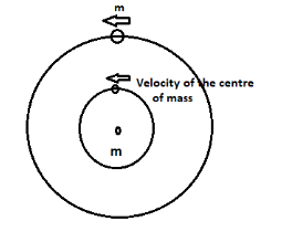
A heavy ring of mass \(m\) is clamped on the periphery of a light circular disc. A small particle having equal mass is clamped at the centre of the disc. The system is rotated in such a way that the centre moves in a circle of radius \(r\) with a uniform speed \(v\). We conclude that an external force
CorrectIncorrectHint
(c)

\(\frac{2 m v^2}{r}\) must be acting on the system.
To solve this, we need to focus on the motion of the Center of Mass (COM) of the entire system.
Locate the Center of Mass:
Let’s analyze the components of the system:
The Disc: Described as “light,” meaning its mass is negligible ( 0 ).
The Particle: Mass \(m\), located at the center of the disc.
The Ring: Mass \(m\), clamped at the periphery.Because the ring is uniform and its center coincides with the center of the disc, the center of mass of the ring is at the center of the disc. Since the particle is also at the center, the Center of Mass of the entire system is located exactly at the center of the disc.
Analyze the Motion:
The problem states that the center of the disc (which we now know is the COM of the system) moves in a circle of radius \(r\) with a uniform speed \(v\).
For any system of mass \(M\) whose center of mass moves in a circle of radius \(r\) with speed \(v\), there must be a net external centripetal force acting on the system. The formula for this force is:
\(
F_{e x t}=M_{t o t a l} \cdot a_{c m}
\)Calculate the Force:
Total Mass \(\left(M_{\text {total }}\right): m(\) particle \()+m(\) ring \()=2 m\).
Centripetal Acceleration ( \(a_{c m}\) ): For circular motion, \(a=\frac{v^2}{r}\).Substituting these into the force equation:
\(
F_{e x t}=(2 m) \cdot\left(\frac{v^2}{r}\right)=\frac{2 m v^2}{r}
\)
Conclusion:
Newton’s Second Law for a system states that \(\sum F_{\text {ext }}=M_{\text {total }} a_{c m}\). Since the system’s COM is accelerating, a net external force of \(\frac{2 m v^2}{r}\) must be present to maintain that motion. - Question 15 of 67
15. Question
The quantities remaining constant in a collision are
CorrectIncorrectHint
(d) momentum, but neither kinetic energy nor temperature.
To understand why this is the most accurate answer, we have to distinguish between different types of collisions and what happens to energy at a microscopic level.
Momentum: Always ConservedIn any collision (elastic or inelastic), the total linear momentum of the system remains constant, provided there is no external net force acting on the system. This is a fundamental law of physics derived from Newton’s Third Law.
Kinetic Energy: Usually ChangesWhile total energy is always conserved, Kinetic Energy (KE) is often not.
In Elastic Collisions: KE is conserved (e.g., subatomic particles or ideal gas molecules).
In Inelastic Collisions: Some KE is converted into other forms of energy, such as sound, potential energy of deformation, or internal thermal energy.
In the Real World: Almost all macroscopic collisions (like two cars hitting or a ball bouncing) are inelastic to some degree, meaning total KE decreases.
Temperature: Usually Increases:When kinetic energy is “lost” in an inelastic collision, it doesn’t disappear; it is transformed. Most of that energy is converted into the random vibrational motion of the atoms within the objects.
Microscopic View: This increase in random atomic motion is exactly what we measure as an increase in temperature.
Therefore, in a typical collision, the temperature of the bodies involved will rise, meaning temperature does not remain constant. - Question 16 of 67
16. Question
The centre of mass of a system of particles is at the origin. It follows that
CorrectIncorrectHint
(e) (None) Actually, none of these statements are necessarily true.
In physics, the center of mass (COM) is defined by the mass-weighted average position of the particles. If the COM is at the origin, it only guarantees that:
\(
\sum m_i r_i=0
\)
This means the “mass-moments” must cancel out, but this can be achieved in many ways that violate your four options. Here is why each one is incorrect:
Number of particles (Left vs. Right):
The COM depends on both mass and distance, not just the count of particles.
Counter-example: You could have one very heavy particle on the left ( 10 kg ) and ten very light particles ( 1 kg each) on the right. If their distances are adjusted correctly, the COM stays at the origin.
Total mass (Left vs. Right):
Even if the masses are unequal, the COM can be at the origin if the lighter mass is further away.
Example: A 1 kg mass at \(x=-10\) and a 10 kg mass at \(x=+1\).
The mass on the right ( 10 kg ) is much greater than the mass on the left ( 1 kg ), but the calculation \(1(-10)+10(1)=0\) puts the COM at the origin.
Number of particles on X-axis vs. Y-axis:
The axes are independent. You could have 100 particles on the X -axis and only 2 on the Y -axis. As long as each axis is internally “balanced” (the sum of moments on that axis is zero), the COM will be at \((0,0)\).
Particles on Positive vs. Negative X-axis
If a particle is on the positive X -axis, there must be mass on the negative side to balance it, but it doesn’t have to be on the X-axis.
Counter-example: Imagine a particle at \((10,0)\). You could balance it with two particles located at \((-5,5)\) and \((-5,-5)\).
Here, there is a particle on the positive X -axis, but no particles on the negative X -axis (they are in the 2nd and 3rd quadrants). Their net effect, however, balances the X-position to zero.The Only Correct Conclusion:
If the center of mass is at the origin, the only thing we can say for sure is:
The sum of the moments of all masses about the origin is zero. ( \(\sum m_i x_i=0\), \(\sum m_i y_i=0\), and \(\sum m_i z_i=0\) ) - Question 17 of 67
17. Question
A body has its centre of mass at the origin. The \(x\)-coordinates of the particles
CorrectIncorrectHint
(c, d) Understanding the Center of Mass
The center of mass is the unique point where the weighted relative position of the distributed mass sums to zero. For a system of discrete particles along the \(x\)-axis, the \(x\)-coordinate of the center of mass ( \(x_{c m}\) ) is calculated as:
\(
x_{c m}=\frac{\sum m_i x_i}{\sum m_i}
\)
Since the problem states the center of mass is at the origin, we know \(x_{c m}=0\). Therefore:
\(
\sum m_i x_i=0
\)
Analyzing the Options
For the sum of mass-weighted positions to equal zero, we can evaluate your options as follows:
(a) May be all positive: If every \(x_i>0\), then the sum \(\sum m_i x_i\) must be positive. This is impossible if \(x_{c m}=0\).
(b) May be all negative: If every \(x_i<0\), then the sum must be negative. This is also impossible.
(c) May be all non-negative: This implies \(x_i \geq 0\). The only way the sum could be zero is if every single particle is located exactly at the origin \(\left(x_i=0\right)\). (While mathematically possible, it doesn’t represent a general “body” with distributed mass.)
(d) May be positive for some and negative for others: To balance the equation to zero, there must be mass on both sides of the origin. Some particles must have positive coordinates to cancel out the negative coordinates of others. - Question 18 of 67
18. Question
In which of the following cases the centre of mass of a rod is certainly not at its centre?
CorrectIncorrectHint
(a, b) Detailed Analysis
To find the center of mass ( \(x_{c m}\) ) of a rod of length \(L\), we use the integral:
\(
x_{c m}=\frac{1}{M} \int_0^L x \lambda(x) d x
\)
where \(\lambda(x)\) is the linear density (mass per unit length). For the center of mass to be at the geometric center ( \(L / 2\) ), the density distribution must be balanced.
\(
\begin{array}{|l|l|l|l|}
\hline \text { Case } & \begin{array}{l}
\text { Density } \\
\text { Distribution }
\end{array} & \text { Result } & \text { Why? } \\
\hline \text { (a) } & \begin{array}{l}
\text { Increases from } \\
\text { left to right }
\end{array} & \begin{array}{l}
\text { Certainly not } \\
\text { at center }
\end{array} & \begin{array}{l}
\text { The right half of the rod is heavier than } \\
\text { the left half, shifting the } C M \text { toward the } \\
\text { right }\left(x_{c m}>L / 2\right) .
\end{array} \\
\hline \text { (b) } & \begin{array}{l}
\text { Decreases from } \\
\text { left to right }
\end{array} & \begin{array}{l}
\text { Certainly not } \\
\text { at center }
\end{array} & \begin{array}{l}
\text { The left half of the rod is heavier than } \\
\text { the right half, shifting the } C M \text { toward } \\
\text { the left }\left(x_{c m}<L / 2\right) .
\end{array} \\
\hline \text { (c) } & \begin{array}{l}
\text { Decreases then } \\
\text { increases }
\end{array} & \begin{array}{l}
\text { Could be at } \\
\text { center }
\end{array} & \begin{array}{l}
\text { If the distribution is symmetric (like a } \\
\text { “V” shape), the mass is balanced on } \\
\text { both sides. }
\end{array} \\
\hline \text { (d) } & \begin{array}{l}
\text { Increases then } \\
\text { decreases }
\end{array} & \begin{array}{l}
\text { Could be at } \\
\text { center }
\end{array} & \begin{array}{l}
\text { If the distribution is symmetric (like a } \\
\text { “Hill” shape), the mass is balanced on } \\
\text { both sides. }
\end{array} \\
\hline
\end{array}
\) - Question 19 of 67
19. Question
If the external forces acting on a system have zero resultant, the centre of mass
CorrectIncorrectHint
(b, c) The Governing Equation
The motion of the center of mass ( \(C M\) ) is determined strictly by the net external force ( \(F_{\text {ext }}\) ) acting on the system:
\(
F_{e x t}=M a_{c m}
\)
Where:
\(M\) is the total mass of the system.
\(a_{c m}\) is the acceleration of the center of mass.
Analysis of the Options
Why (b) is correct: “Must not accelerate”
If the resultant external force is zero \(\left(F_{\text {ext }}=0\right)\), then according to the formula:
\(
0=M a_{c m} \Longrightarrow a_{c m}=0
\)
Since the acceleration is zero, the center of mass cannot change its velocity.
Why (c) is correct: “May move”
Acceleration being zero does not mean the object is stationary. It means the velocity is constant. There are two possibilities for the center of mass:
If it was at rest, it stays at rest (velocity \(=0\) ).
If it was already moving, it continues to move in a straight line at a constant speed \((\) velocity \(=\) constant \()\).
Therefore, the center of mass may move, provided it does so without accelerating.
Why (a) and (d) are incorrect
(a) must not move: This is too restrictive. It ignores the possibility of the system having initial momentum.
(d) may accelerate: This is impossible. Acceleration requires a non-zero net external force. Internal forces (like explosions or collisions within the system) cannot accelerate the center of mass. - Question 20 of 67
20. Question
A nonzero external force acts on a system of particles. The velocity and the acceleration of the centre of mass are found to be \(v_0\) and \(a_0\) at an instant \(t\). It is possible that
CorrectIncorrectHint
(b, d)
When a nonzero external force \(\left(F_{\text {ext }} \neq 0\right)\) acts on a system, the motion of the center of mass \((C M)\) is governed by the following fundamental relationships:
1. Acceleration: \(F_{\text {ext }}=M a_{c m}\)
2. Velocity: \(a_{c m}=\frac{d v_{c m}}{d t}\)Analysis of Possibilities
Because a nonzero force is acting, we can conclude the following about the acceleration and velocity at an instant \(t\) :
Acceleration ( \(a_0\) ): Since \(F_{\text {ext }} \neq 0\) and mass \(M\) is positive, the acceleration \(a_{c m}\) must be nonzero ( \(a_0 \neq 0\) ).
Velocity ( \(v_0\) ): The velocity \(v_{c m}\) can be anything at a specific instant. It depends entirely on the system’s previous motion (initial conditions).\(
\begin{array}{|l|l|l|l|}
\hline \text { Scenario } & \begin{array}{l}
\text { Velocity } \\
v_0
\end{array} & \begin{array}{l}
\text { Acceleration } \\
a_0
\end{array} & \text { Real-World Example } \\
\hline \begin{array}{l}
\text { Instantaneous } \\
\text { Rest }
\end{array} & \begin{array}{l}
\text { Zero }( \\
\left.v_0=0\right)
\end{array} & \begin{array}{l}
\text { Non-zero ( } \\
\left.a_0 \neq 0\right)
\end{array} & \begin{array}{l}
\text { A ball thrown upward at its highest } \\
\text { point. Gravity (external force) is } \\
\text { still acting, so it is accelerating } \\
\text { down, but its velocity is zero for } \\
\text { that split second. }
\end{array} \\
\hline \text { Speeding Up } & \begin{array}{l}
\text { Non-zero } \\
\left(v_0 \neq 0\right)
\end{array} & \begin{array}{l}
\text { Non-zero ( } \\
a_0 \neq 0 \text { ) }
\end{array} & \begin{array}{l}
\text { A rocket launching. It already has } \\
\text { upward velocity, and the external } \\
\text { thrust continues to accelerate it } \\
\text { further. }
\end{array} \\
\hline \text { Slowing Down } & \begin{array}{l}
\text { Non-zero } \\
\left(v_0 \neq 0\right)
\end{array} & \begin{array}{l}
\text { Non-zero ( } \\
\left.a_0 \neq 0\right)
\end{array} & \begin{array}{l}
\text { A car braking. It has forward } \\
\text { velocity, but the external friction } \\
\text { force creates acceleration in the } \\
\text { opposite direction. }
\end{array} \\
\hline
\end{array}
\) - Question 21 of 67
21. Question
Two balls are thrown simultaneously in air. The acceleration of the centre of mass of the two balls while in air
CorrectIncorrectHint
(d) Identify the External Forces: Once the balls are released into the air (ignoring air resistance), the only external force acting on each ball is gravity. For two balls with masses \(m_1\) and \(m_2\) :
Force on ball 1: \(F_1=m_1 g\) (downward)
Force on ball 2: \(F_2=m_2 g\) (downward)
Calculate the Net External Force: The total external force ( \(F_{\text {ext }}\) ) acting on the system is the sum of these individual forces:
\(
F_{e x t}=m_1 g+m_2 g=\left(m_1+m_2\right) g
\)
Apply Newton’s Second Law for a System: The acceleration of the center of mass \(\left(a_{c m}\right)\) is defined by:
\(
F_{e x t}=M a_{c m}
\)
Where \(M\) is the total mass of the system ( \(m_1+m_2\) ).
Solve for \(a_{c m}\) :
\(
\begin{gathered}
\left(m_1+m_2\right) g=\left(m_1+m_2\right) a_{c m} \\
a_{c m}=g
\end{gathered}
\)
Thus, the acceleration of the center of mass is always equal to the acceleration due to gravity, \(g\), regardless of their masses, speeds, or directions of motion. - Question 22 of 67
22. Question
A block moving in air breaks in two parts and the parts separate
CorrectIncorrectHint
(a, d) (a) Total momentum must be conserved: This is a fundamental law of physics. As long as there is no external resultant force ( \(F_{\text {ext }}=0\) ), the total linear momentum of the system remains constant, regardless of what happens internally (collisions, explosions, etc.). The internal forces of the “breaking” or “explosion” do not change the total momentum of the system. Therefore, the total momentum remains constant.
(b) Total kinetic energy must be conserved: This is false for most cases. Kinetic energy is only conserved in “perfectly elastic” collisions. In the real world, some energy is always lost.
(c) Total momentum must change: This is false. Internal forces cannot change the momentum of the system’s center of mass.
(d) Total Kinetic energy changes during an explosion because internal potential energy (e.g., chemical energy in an explosive) is converted into the kinetic energy of the fragments, or potentially into other forms like heat and sound. The initial kinetic energy of the whole block is different from the final total kinetic energy of the two parts. This option is correct. - Question 23 of 67
23. Question
In an elastic collision
CorrectIncorrectHint
(b, c, d) Analysis of the Options
(b) and (d) are Correct (Momentum):
Linear Momentum is conserved in all collisions where no external force acts.
Therefore, the final linear momentum is equal to the initial linear momentum (d), and it remains constant throughout the entire process (b).
(c) is Correct (Kinetic Energy):
In an elastic collision, the total kinetic energy after the collision is equal to the total kinetic energy before the collision ( \(K_i=K_f\) ). This is the defining characteristic of an elastic collision.
(a) is Incorrect (The “Constant” Trap)”
While the final kinetic energy equals the initial kinetic energy, the kinetic energy does not remain constant during the collision.
At the moment of impact, the bodies deform slightly. During this brief instant, some of the kinetic energy is temporarily converted into elastic potential energy. Once the bodies spring apart, that potential energy is converted back into kinetic energy.
Summary: Comparision of states
\(
\begin{array}{lll}
\text { State } & \text { Linear Momentum } & \text { Kinetic Energy } \\
\text { Before Collision } & P & K \\
\text { During Collision } & P(\text { Constant }) & \text { Decreased }(\text { Converted to Potential }) \\
\text { After Collision } & P(\text { Final }=\text { Initial }) & K(\text { Final }=\text { Initial })
\end{array}
\) - Question 24 of 67
24. Question
A ball hits a floor and rebounds after an inelastic collision. In this case
CorrectIncorrectHint
(c, d) (a) Momentum of the ball (Incorrect)
Momentum is a vector quantity ( \(p=m v\) ). Even if the ball rebounded with the same speed, its direction changed from downward to upward. Furthermore, because it is an inelastic collision, it loses speed upon impact. Therefore, the momentum of the ball definitely changes.
(b) Mechanical energy of the ball (Incorrect)Mechanical energy is the sum of kinetic and potential energy. During an inelastic collision, some kinetic energy is converted into non-mechanical forms like heat, sound, and internal deformation energy. Thus, the mechanical energy of the ball decreases.
(c) Total momentum of the ball and the Earth (Correct)According to the law of conservation of momentum, the total momentum of an isolated system remains constant. While the ball’s momentum changes significantly, it exerts an equal and opposite force on the Earth. The Earth recoils (though by an immeasurably small amount due to its massive size). The vector sum of the momentum of the ball and the Earth remains the same.
(d) Total energy of the ball and the Earth (Correct)While mechanical energy is lost, the total energy (including heat, sound, and internal energy) is always conserved in any closed system. The energy “lost” by the ball doesn’t disappear; it simply transfers to the surroundings (the floor and the air) as thermal energy and acoustic energy.
- Question 25 of 67
25. Question
Let \(\vec{A}\) be a unit vector along the axis of rotation of a purely rotating body and \(\vec{B}\) be a unit vector along the velocity of a particle \(P[latex] of the body away from the axis. The value of [latex]\vec{A} \cdot \vec{B}\) is
CorrectIncorrectHint
(c) Direction of the Axis ( \(A\) ): The axis of rotation is the line about which every particle in the body moves in a circle. The unit vector \(A\) points along this line (the \(z\)-axis in many standard coordinate systems).
Direction of Velocity ( \(B\) ): For any particle \(P\) at a distance \(r\) from the axis, its path is a circle in a plane perpendicular to the axis of rotation. The velocity vector \(v\) of that particle is always tangential to its circular path.
The Relationship ( \(v=\omega \times r\) ): Mathematically, the velocity \(v\) is given by the cross product of the angular velocity \(\omega\) and the position vector \(r\) :
\(
v=\omega \times r
\)
Since \(\omega\) lies along the axis of rotation (the direction of \(A\) ), the properties of the cross product dictate that the resulting velocity vector \(v\) must be perpendicular to \(\omega\).
The Dot Product \((A \cdot B)\) :
\(A\) is along the axis.
\(B\) is along the velocity (tangential).
Since the velocity vector is perpendicular to the axis of rotation:
\(
A \perp B \Longrightarrow \theta=90^{\circ}
\)
The dot product is defined as:
\(
A \cdot B=|A||B| \cos \left(90^{\circ}\right)
\)
Since \(\cos \left(90^{\circ}\right)=0\), the value is:
\(
A \cdot B=0
\) - Question 26 of 67
26. Question
A body is uniformly rotating about an axis fixed in an inertial frame of reference. Let \(\vec{A}\) be a unit vector along the axis of rotation and \(\vec{B}\) be the unit vector along the resultant force on a particle \(P\) of the body away from the axis. The value of \(\vec{A} \cdot \vec{B}\) is
CorrectIncorrectHint
(c) Direction of the Axis ( \(A\) ): The unit vector \(A\) points along the fixed axis of rotation. In uniform rotation, the angular velocity vector \(\omega\) also lies along this axis.
The Resultant Force ( \(B\) ): For a particle \(P\) in a uniformly rotating body, the particle moves in a circle of radius \(r\) in a plane perpendicular to the axis of rotation.
Since the rotation is uniform (constant angular velocity), there is no tangential acceleration ( \(a_t=0\) ).
The only acceleration is centripetal acceleration \(\left(a_c=\omega^2 r\right)\), which points directly toward the axis of rotation.
By Newton’s Second Law ( \(F=m a\) ), the resultant force \(F\) must also point directly toward the axis of rotation.
The Geometric Relationship: Because the particle moves in a plane perpendicular to the axis, the “radial” line (the path of the force) is also in that same plane. Therefore, the force vector \(F\) is perpendicular to the axis of rotation.
\(A\) is the unit vector along the axis.
\(B\) is the unit vector along the force (radial).
Since \(A \perp B\), the angle \(\theta\) between them is \(90^{\circ}\).
Calculating the Dot Product: The dot product of two vectors is defined as:
\(
A \cdot B=|A||B| \cos \theta
\)
Since these are unit vectors \((|A|=|B|=1)\) and \(\theta=90^{\circ}\) :
\(
\begin{gathered}
A \cdot B=(1)(1) \cos \left(90^{\circ}\right) \\
A \cdot B=0
\end{gathered}
\)
What if the rotation was not uniform?
If the rotation were accelerating (non-uniform), there would be an additional tangential force. However, because the tangential force also lies in the plane perpendicular to the axis, the resultant force would still be in that plane. Consequently, the dot product \(A \cdot B\) would still be 0. - Question 27 of 67
27. Question
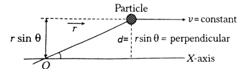
A particle moves with a constant velocity parallel to the \(X\)-axis. Its angular momentum with respect to the origin
CorrectIncorrectHint
(b)

\(L=m(\vec{r} \times \vec{v})\), where \(m\) is mass, \(\overrightarrow{ r }\) is the position vector from the origin, and \(\overrightarrow{ v }\) is the velocity vector.
Constant Motion: If the particle moves parallel to the X-axis with constant velocity \((v)\), its linear momentum \((m v)\) is constant, and the perpendicular distance \((y=d=r\sin \theta)\) from the origin to its path also remains constant.
\(r \sin \theta\) represents the perpendicular distance \((d)\) from the origin to the line of motion.
Result: Since \(m\), \(v\), and perpendicular distance \(d\) are all constant, the magnitude of the angular momentum, \(L=m v \times\) (perpendicular distance), remains constant. - Question 28 of 67
28. Question
A body is in pure rotation. The linear speed \(v\) of a particle, the distance \(r\) of the particle from the axis and the angular velocity \(\omega\) of the body are related as \(\omega=\frac{v}{r}\). Thus
CorrectIncorrectHint
(d) Defining Pure Rotation:
In a purely rotating rigid body, every particle (except those on the axis) moves in a circle. The fundamental characteristic of a rigid body is that the relative positions of its particles remain fixed.
For the body to maintain its shape as it turns, every particle must complete one full revolution in the exact same amount of time.
Analysis of the Variables:
We are given the relationship:
\(
\omega=\frac{v}{r}
\)
While it mathematically looks like \(\omega[latex] depends on [latex]r\), we must consider how \(v\) (linear speed) changes as we move further from the axis:
Particles closer to the axis (small \(r\) ) travel a shorter distance (smaller circumference) in one revolution.
Particles farther from the axis (large \(r\) ) travel a much longer distance in the same amount of time.
Therefore, the linear speed \(v\) is directly proportional to the radius \((v \propto r)\).
Why (d) is Correct?
Because \(v\) increases at the same rate as \(r\) increases, the ratio \(\frac{v}{r}\) remains constant for every particle in the body.
\(
\text { If } v_1=\omega r_1 \text { and } v_2=\omega r_2, \text { then } \frac{v_1}{r_1}=\frac{v_2}{r_2}=\omega
\)Thus, \(\omega\) is a property of the entire body, not a property of a specific particle’s location.
Summary Table:
\(
\begin{array}{lll}
\text { Quantity } & \text { Variable } & \text { Dependency on } r \\
\text { Angular Velocity } & \omega & \text { Independent (Same for all particles) } \\
\text { Linear Speed } & v & \text { Proportional }(v=\omega r) \\
\text { Centripetal Accel. } & a_c & \text { Proportional }\left(a_c=\omega^2 r\right)
\end{array}
\) - Question 29 of 67
29. Question
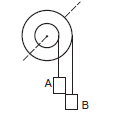
Figure below shows a small wheel fixed coaxially on a bigger one of double the radius. The system rotates about the common axis. The strings supporting \(A\) and \(B\) do not slip on the wheels. If \(x\) and \(y\) be the distances travelled by \(A\) and \(B\) in the same time interval, then
 CorrectIncorrect
Hint
(c) Take the radius of pulley associated with mass A as \(R\) and that of B as \(2 R\).
Angular velocity of mass \(A , v_A=\omega R\)
Angular velocity of mass \(B , v_B=\omega \times 2 R\)
Distance travelled by \(A =x=v_A t=\omega R t\)
Distance travelled by \(B =y=v_B t=\omega \times 2 R \times t\)
Substituting value of \(\omega R t\) from equation \(x=v_A t=\omega R t\) to equation \(y=v_B t=\omega \times 2 R \times t\)
We get, \(y=\omega \times 2 R \times t=2 \omega R t=2 x\)
\(
y=2 x
\) - Question 30 of 67
30. Question
A body is rotating uniformly about a vertical axis fixed in an inertial frame. The resultant force on a particle of the body not on the axis is
CorrectIncorrectHint
(c) The Path of the Particle When a body rotates about a fixed vertical axis, any particle \(P\) within that body (not on the axis) moves in a horizontal circle. The center of this circle lies on the axis of rotation.
Uniform Rotation and Acceleration “Uniformly rotating” means the angular velocity \(\omega\) is constant. For a particle in uniform circular motion:
(i) Tangential acceleration ( \(a_t\) ) is zero because the speed is constant.
(ii) Centripetal acceleration ( \(a_c\) ) is present because the direction of motion is constantly changing.
The centripetal acceleration is given by \(a_c=\omega^2 r\), and it always points radially inward toward the center of the circle (the axis).The Resultant Force According to Newton’s Second Law ( \(F=m a\) ), the resultant force \(F\) must be in the same direction as the acceleration.
(i) Since the acceleration is horizontal and points toward the axis, the force is horizontal.
(ii) Since the force vector points directly at the center of the particle’s circular path (which is a point on the axis), the force is intersecting the axis.
Why the other options are incorrect:
(a) Vertical: There is no net vertical acceleration. While gravity acts downward, it is balanced by internal structural forces within the rigid body.
(b) Skew with the axis: “Skew” means the lines do not intersect and are not parallel. A centripetal force, by definition, must point directly at the axis, meaning it must intersect it. - Question 31 of 67
31. Question
A body is rotating nonuniformly about a vertical axis fixed in an inertial frame. The resultant force on a particle of the body not on the axis is
CorrectIncorrectHint
(b) When a body rotates non-uniformly, it means its angular velocity ( \(\omega\) ) is changing. This introduces an additional component of force compared to uniform rotation.
Step-by-Step Analysis
Step 1: The Plane of Motion Even if the rotation is non-uniform, every particle in the body still moves in a horizontal circle centered on the vertical axis. Therefore, all acceleration and all resultant forces must lie within this horizontal plane.
Step 2: The Two Components of Acceleration For a particle in non-uniform circular motion, there are two components of acceleration:
– Centripetal Acceleration ( \(a_c\) ): Points radially toward the axis \(\left(a_c=\omega^2 r\right)\).
– Tangential Acceleration \(\left(a_t\right)\) : Points along the tangent to the circle \(\left(a_t=\alpha r\right.\), where \(\alpha\) is the angular acceleration).
Step 3: The Resultant Force Vector The total acceleration \(a\) is the vector sum of \(a_c\) and \(a_t\). By Newton’s Second Law ( \(F=m a\) ), the resultant force \(F\) also has two components:
– A radial component (pointing at the axis).
– A tangential component (perpendicular to the radius).
Step 4: Why the Force is “Skew”
– Horizontal: Both components are horizontal, so the resultant is horizontal.
– Skew with the axis: Because the resultant force has a tangential component, it no longer points directly at the axis of rotation. In three-dimensional space, a horizontal line that does not point at a vertical axis and is not parallel to it is considered skew to that axis. It will “pass by” the axis rather than intersect it.
Comparision Summary:
\(
\begin{array}{lll}
\text { Type of Rotation } & \text { Force Direction } & \text { Relation to Axis } \\
\text { Uniform } & \text { Purely Radial } & \text { Horizontal and Intersecting } \\
\text { Non-Uniform } & \text { Radial + Tangential } & \text { Horizontal and Skew }
\end{array}
\) - Question 32 of 67
32. Question
Let \(\vec{F}\) be a force acting on a particle having position vector \(\vec{r}\). Let \(\)\vec{\tau}\(\) be the torque of this force about the origin, then
CorrectIncorrectHint
(a) Definition of Torque: The torque vector \(\vec{\tau}\) is defined as the cross product of the position vector \(\vec{r}\) and the force vector \(\vec{F}\).
\(\vec{\tau}=\vec{r} \times \vec{F}\)
Properties of the Cross Product: A fundamental property of the cross product is that the resulting vector \((\vec{\tau})\) is perpendicular (orthogonal) to both of the original vectors ( \(\vec{r}\) and \(\vec{F}\) ).
Dot Product and Orthogonality: The dot product of two non-zero vectors is zero if and only if the vectors are orthogonal.
Applying the Property:
(a) Since \(\vec{\tau}\) is perpendicular to \(\vec{r}\), their dot product is zero:
\(
\vec{r} \cdot \vec{\tau}=\vec{r} \cdot(\vec{r} \times \vec{F})=0
\)
(b) Since \(\vec{\tau}\) is perpendicular to \(\vec{F}\), their dot product is also zero:
\(
\vec{F} \cdot \vec{\tau}=\vec{F} \cdot(\vec{r} \times \vec{F})=0
\) - Question 33 of 67
33. Question
One end of a uniform rod of mass \(m\) and length \(l\) is clamped. The rod lies on a smooth horizontal surface and rotates on it about the clamped end at a uniform angular velocity \(\omega\). The force exerted by the clamp on the rod has a horizontal component
CorrectIncorrectHint
(d) To find the force exerted by the clamp, we need to look at the centripetal force required to keep the rod rotating.
Step 1: Centripetal Force and the Center of Mass:
For any rigid body rotating about a fixed axis, the net external force required to keep it in uniform rotation is equal to the mass of the body multiplied by the centripetal acceleration of its Center of Mass (CM).
– Mass of the rod: \(m\)
– Location of \(C M\) : For a uniform rod of length \(l\), the center of mass is at its geometric center, which is at a distance \(r_{c m}=\frac{l}{2}\) from the clamped end (the axis).
– Angular Velocity: \(\omega\) (constant).
Step 2: Calculating the Force:
The centripetal acceleration \(\left(a_c\right)\) of the center of mass is:
\(
a_c=\omega^2 r_{c m}=\omega^2\left(\frac{l}{2}\right)
\)
According to Newton’s Second Law ( \(F=m a\) ), the horizontal component of the force exerted by the clamp must provide this acceleration:
\(
\begin{gathered}
F_{\text {clamp }}=m \cdot a_c \\
F_{\text {clamp }}=m \cdot \omega^2\left(\frac{l}{2}\right) \\
F_{\text {clamp }}=\frac{1}{2} m \omega^2 l
\end{gathered}
\)
Step 3: Why it’s not the other options
(a) \(m \omega^2 l\) : This would be the force if the entire mass of the rod were concentrated at the very tip (the far end).
(b) Zero: A force is necessary to change the direction of the rod’s velocity (centripetal force). Since the surface is “smooth,” there is no friction to provide this, so the clamp must do it.
(c) \(m g\) : This is the vertical weight of the rod. While the clamp might exert a vertical force to counteract gravity, the question specifically asks for the horizontal component. - Question 34 of 67
34. Question
A uniform rod is kept vertically on a horizontal smooth surface at a point \(O\). If it is rotated slightly and released, it falls down on the horizontal surface. The lower end will remain
CorrectIncorrectHint
(c) This is a classic problem involving the motion of the Center of Mass (CM) when external horizontal forces are absent.
Step 1: Analysis of External Forces
To determine how the rod moves, we must look at the forces acting on it in the horizontal direction:
– Gravity ( \(m g\) ): Acts vertically downward.
– Normal Force ( \(N\) ): Acts vertically upward from the surface.
– Friction: The problem states the surface is smooth, meaning there is no friction.Since there are no horizontal external forces acting on the rod ( \(\sum F_x=0\) ), the horizontal position of the Center of Mass must remain constant.
Step 2: Motion of the Center of Mass (CM)
– Initial State: The rod is vertical. For a uniform rod of length \(l\), the CM is located at its geometric center. Directly below the CM is the point \(O\) on the surface.
– Falling State: As the rod falls, it rotates and its CM moves downward. However, because there is no horizontal force to push the rod left or right, the CM falls in a perfectly vertical line.
Step 3: Final Position of the Lower End
When the rod finally lies flat on the horizontal surface:
1. The Center of Mass is still directly above/at the original horizontal position of \(O\).
2. Since the rod is uniform, the distance from the CM to the lower end is \(l / 2\).
3. Therefore, if the CM is at \(O\), the lower end must be at a distance of \(l / 2\) from \(O\).
Summary of the motion:
\(
\begin{array}{lll}
\text { Component } & \text { Horizontal Motion } & \text { Vertical Motion } \\
\text { Center of Mass } & \text { Stationary (at } O \text { ) } & \text { Accelerates downward } \\
\text { Lower End } & \text { Slides away from } O & \text { Stays on the surface } \\
\text { Upper End } & \text { Slides away from } O & \text { Falls toward the surface }
\end{array}
\) - Question 35 of 67
35. Question
A circular disc \(A\) of radius \(r\) is made from an iron plate of thickness \(t\) and another circular disc \(B\) of radius \(4 r\) is made from an iron plate of thickness \(t / 4\). The relation between the moments of inertia \(I_A\) and \(I_B\) is
CorrectIncorrectHint
(c) To find the relationship between the moments of inertia, we need to calculate the mass of each disc and then apply the formula for the moment of inertia of a disc.
Step 1: Mass Calculation
The mass ( \(m\) ) of a disc is given by:
\(
m=\text { Volume × Density }=\left(\pi r^2 \times t\right) \times \rho
\)
For Disc A:
\(
m_A=\pi r^2 t \rho
\)
For Disc B: Radius is \(4 r\) and thickness is \(t / 4\).
\(
m_B=\pi(4 r)^2\left(\frac{t}{4}\right) \rho=\pi\left(16 r^2\right)\left(\frac{t}{4}\right) \rho=4 \pi r^2 t \rho
\)
So, \(m_B=4 m_A\).
Step 2: Moment of Inertia (MOI) Calculation
The moment of inertia ( \(I\) ) of a uniform circular disc about its central axis is:
\(
I=\frac{1}{2} m r^2
\)
For Disc A:
\(
I_A=\frac{1}{2} m_A r^2
\)
For Disc B:
\(
I_B=\frac{1}{2} m_B(4 r)^2
\)
Substitute \(m_B=4 m_A\) :
\(
\begin{aligned}
I_B & =\frac{1}{2}\left(4 m_A\right)\left(16 r^2\right) \\
I_B & =64\left(\frac{1}{2} m_A r^2\right)
\end{aligned}
\)
So, \(I_B=64 I_A\).
Step 3: Conclusion
Comparing the two values:
\(
I_B=64 I_A
\)
Clearly, \(I_A<I_B\). - Question 36 of 67
36. Question
Equal torques act on the discs \(A\) and \(B\) of the previous problem, initially both being at rest. At a later instant, the linear speeds of a point on the rim of \(A\) and another point on the rim of \(B\) are \(v_A\) and \(v_B\) respectively. We have
CorrectIncorrectHint
(a) To solve this, we need to relate the torque applied to the resulting linear speed of a point on the rim after a certain time interval \(t\).
Step 1: Finding Angular Acceleration ( \(\alpha\) )
From Newton’s Second Law for rotation, the torque \(\tau\) and moment of inertia \(I\) are related to angular acceleration by:
\(
\tau=I \alpha \Longrightarrow \alpha=\frac{\tau}{I}
\)
From the previous problem, we know that \(I_B=64 I_A\). If equal torques ( \(\tau\) ) are applied to both:
For Disc A: \(\alpha_A=\frac{\tau}{I_A}\)
For Disc B: \(\alpha_B=\frac{\tau}{I_B}=\frac{\tau}{64 I_A}\)
This shows that \(\alpha_A=64 \alpha_B\). Disc A accelerates much faster because it has much less rotational inertia.
Step 2: Finding Angular Velocity ( \(\omega\) )
Starting from rest, the angular velocity after time \(t\) is:
\(
\omega=\alpha t
\)
For Disc A: \(\omega_A=\alpha_A t\)
For Disc B: \(\omega_B=\alpha_B t=\left(\frac{\alpha_A}{64}\right) t=\frac{\omega_A}{64}\)
Step 3: Finding Linear Speed ( \(v\) ) on the Rim
The linear speed of a point on the rim is given by \(v=\omega R\).
For Disc A (Radius \(r\) ):
\(
v_A=\omega_A r
\)
For Disc B (Radius \(4 r\) ):
\(
v_B=\omega_B(4 r)
\)
Substitute \(\omega_B=\frac{\omega_A}{64}\) :
\(
v_B=\left(\frac{\omega_A}{64}\right)(4 r)=\frac{\omega_A r}{16}
\)
Step 4: Conclusion
Comparing the two results:
\(
v_B=\frac{v_A}{16}
\)
Therefore, \(v_A=16 v_B\), which means \(v_A>v_B\).
Even though Disc B has a larger radius (which usually helps increase linear speed), its moment of inertia is so much larger ( \(64 \times\) ) that it barely begins to spin compared to Disc A. - Question 37 of 67
37. Question
A closed cylindrical tube containing some water (not filling the entire tube) lies in a horizontal plane. If the tube is rotated about a perpendicular bisector, the moment of inertia of water about the axis
CorrectIncorrectHint
(a) To understand why, we need to look at how the distribution of the water changes when the tube starts rotating.
Step 1: Initial State (At Rest)
When the tube is lying horizontally and not rotating, the water settles at the bottom of the cylinder, distributed evenly along the length of the tube (or centered if the tube is perfectly level). The “perpendicular bisector” is an axis passing through the center of the tube’s length, perpendicular to its longitudinal axis.
Step 2: Effect of Rotation (Centrifugal Effect)
When the tube begins to rotate about its center, every particle of water experiences a “centrifugal force” (in the rotating frame) pushing it away from the axis of rotation.
– Because the water is fluid and not filling the entire tube, it is free to move.
– The water will move toward the outer ends of the cylinder, away from the central axis.
Step 3: Moment of Inertia Calculation
The moment of inertia ( \(I\) ) for a system of particles is defined as:
\(
I=\sum m_i r_i^2
\)
where \(r\) is the distance of the mass from the axis of rotation.
– When the water moves toward the ends of the tube, its average distance \((r)\) from the central axis increases.
– Since \(I\) is proportional to the square of the distance \(\left(r^2\right)\), as the water moves further from the center, the moment of inertia of the water increases.
Step 4: Why the other options are incorrect
(b) & (c): These would only be true if the water were restricted from moving or if it moved toward the center, which contradicts the physics of rotation.
(d): The moment of inertia depends on the square of the distance \(\left(r^2\right)\) and the distribution of mass. It does not depend on the direction of rotation (clockwise vs. anticlockwise), as the centrifugal effect pushes mass outward in both cases.Summary
In any system where mass is free to move radially, rotation will tend to throw that mass outward. Moving mass away from the axis always results in an increase in the moment of inertia. - Question 38 of 67
38. Question
The moment of inertia of a uniform semicircular wire of mass \(M\) and radius \(r\) about a line perpendicular to the plane of the wire through the centre is
CorrectIncorrectHint
(a) Step 1: The Fundamental Definition
The moment of inertia \((I)\) for any object about an axis is given by the integral:
\(
I=\int r^2 d m
\)
where \(r\) is the perpendicular distance of the mass element \(d m\) from the axis of rotation.
Step 2: Analysis of the Semicircular Wire
In this specific problem:
– The axis is perpendicular to the plane of the wire.
– The axis passes through the center of the circle of which the wire is a part.
– For a semicircular wire of radius \(r\), every single point on that wire is at the exact same distance \((r)\) from the center.
Step 3: Calculation
Since the distance \(r\) is constant for every mass element \(d m\) on the wire, we can pull \(r^2\) out of the integral:
\(
I=r^2 \int d m
\)
The integral \(\int d m\) is simply the total mass \((M)\) of the semicircular wire. Therefore:
\(
I=r^2 \int d m
\)
Summary
The moment of inertia only depends on how far the mass is from the axis. Since \(100 \%\) of the mass of the semicircular wire is located at the distance \(r\) from the central axis, its moment of inertia is simply \(M r^2\), regardless of the fact that it is only half of a circle. - Question 39 of 67
39. Question
Let \(I_1\) and \(I_2\) be the moments of inertia of two bodies of identical geometrical shape, the first made of aluminium and the second of iron.
CorrectIncorrectHint
(a) The moment of inertia of an object depends on two main factors: the distribution of its mass (shape and size) and the total mass of the object.
Analysis of Mass:
The problem states that the two bodies have identical geometrical shapes. This means their volumes ( \(V[latex] ) are exactly the same. The mass ( [latex]m\) ) of an object is calculated as:
\(
m=\text { Volume × Density }(\rho)
\)
Body 1 (Aluminium): \(m_1=V \times \rho_{A l}\)
Body 2 (Iron): \(m_2=V \times \rho_{F e}\)
Iron is significantly denser than aluminium ( \(\rho_{F e} \approx 7.8 g / cm ^3\) vs. \(\rho_{A l} \approx 2.7 g / cm ^3\) ).
Therefore, for the same volume:
\(
m_2>m_1
\)
Because \(I\) is directly proportional to the mass \((I \propto m)\), and we know the iron body is heavier:
\(
I_2>I_1 \Longrightarrow I_1<I_2
\) - Question 40 of 67
40. Question
A body having its centre of mass at the origin has three of its particles at \((a, 0,0),(0, a, 0),(0,0, a)\). The moments of inertia of the body about the \(X\) and \(Y\) axes are \(0.20 kg- m ^2\) each. The moment of inertia about the \(Z\)-axis
CorrectIncorrectHint
(d) Step 1: Define Moments of Inertia
The moment of inertia about an axis for a system of particles is defined as \(I =\sum m _{ i } r _{ i }^2\), where \(r _{ i }\) is the perpendicular distance of the \(i\)-th particle of mass \(m _{ i }\) from the axis.
The moments of inertia about the \(X , Y\), and Z axes are:
\(
I_X=\sum_i m_i\left(y_i^2+z_i^2\right)
\)
\(
I_Y=\sum_i m_i\left(x_i^2+z_i^2\right)
\)
\(
I_Z=\sum_i m_i\left(x_i^2+y_i^2\right)
\)
Step 2: Set Up Equations from Given Information
Let \(m_1, m_2, m_3\) be the masses of the particles at \((a, 0,0),(0, a, 0)\), and \((0,0, a)\) respectively. There might be other particles, which we group as a remainder of the body (R).
Given \(I _{ X }=0.20 kg- m ^2\) and \(I _{ Y }=0.20 kg- m ^2\).
\(
\begin{gathered}
I_X=m_2 a^2+m_3 a^2+I_{X, R}=0.20 \\
I_Y=m_1 a^2+m_3 a^2+I_{Y, R}=0.20 \\
I_Z=m_1 a^2+m_2 a^2+I_{Z, R}=?
\end{gathered}
\)
We are also given that the center of mass is at the origin, which implies certain conditions on the distribution of the remainder mass (R), but it doesn’t give specific values for the masses or the exact distribution of R.
For example, from \(I _{ X }= I _{ Y }\), we get \(m _2 a^2+ m _3 a^2+ I _{ X , R }= m _1 a^2+ m _3 a^2+ I _{Y, R ^{\prime}}\), which simplifies to \(m_2 a^2+I_{X, R}=m_1 a^2+I_{Y, R}\).
However, we still have too many unknown variables ( \(m _1, m _2, m _3\), and the specific distributions \(\left.I_{X, R}, I_{Y, R}, I_{Z, R}\right)\) to solve for \(I_Z\) definitively.
The moment of inertia about the Z-axis (d) cannot be deduced with this information. - Question 41 of 67
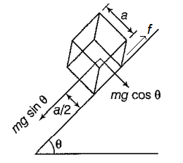
41. Question
A cubical block of mass \(M\) and edge \(a\) slides down a rough inclined plane of inclination \(\theta\) with a uniform velocity. The torque of the normal force on the block about its centre has a magnitude
CorrectIncorrectHint
(d)

Analysis of the Forces:
For a block of mass \(M\) and side \(a\) sliding down an incline of angle \(\theta\) at a constant velocity, the net force and the net torque about its center of mass must be zero.
The forces acting on the block are:
Gravity ( \(M g\) ): Acts downward through the center of mass. Its torque about the center is zero.
Friction (f): Acts upward along the surface of the incline. It acts at a distance of \(a / 2\) from the center.
Normal Force ( \(N\) ): Acts perpendicular to the incline.
The Torque of Friction:
Since the block is moving at a constant velocity, the force of friction must exactly balance the component of gravity pulling the block down the slope:
\(
f=M g \sin \theta
\)
This friction force acts at the base of the block, which is a perpendicular distance of \(r_{\perp}=a / 2\) from the center of mass. The torque due to friction \(\left(\tau_f\right)\) is:
\(
\tau_f=f \times \frac{a}{2}=(M g \sin \theta) \frac{a}{2}=\frac{1}{2} M g a \sin \theta
\)
The Torque of the Normal Force:
Because the block is not rotating (it is in rotational equilibrium), the total torque about the center of mass must be zero:
\(
\sum \tau_{\text {center }}=\tau_N+\tau_f+\tau_g=0
\)
Since \(\tau_g=0\), the torque produced by the normal force \(\left(\tau_N\right)\) must be equal and opposite to the torque produced by friction to prevent the block from “tipping” forward:
\(
\begin{gathered}
\left|\tau_N\right|=\left|\tau_f\right| \\
\tau_N=\frac{1}{2} M g a \sin \theta
\end{gathered}
\)
Why the Normal Force creates Torque?
In a static or uniform-velocity situation on an incline, the normal force does not act exactly through the center of the base. It shifts slightly “downhill” from the center of the block’s base. This shift creates the necessary counter-torque to balance the friction. - Question 42 of 67
42. Question
A thin circular ring of mass \(M\) and radius \(r\) is rotating about its axis with an angular speed \(\omega\). Two particles having mass \(m\) each are now attached at diametrically opposite points. The angular speed of the ring will become
CorrectIncorrectHint
(b) Step 1: Calculate the initial moment of inertia and angular momentum
The initial moment of inertia \(\left( I _{ i }\right)\) of the ring about its axis is \(I _{ i }= M r^2\). The initial angular momentum ( \(L_i\) ) is the product of the initial moment of inertia and the initial angular speed \((\omega)\) :
\(
L_i=I_i \omega=M r^2 \omega
\)
Step 2: Calculate the final moment of inertia
Two particles of mass \(m\) each are added at diametrically opposite points (at radius \(r\) ). The total final moment of inertia \(\left( I _{ f }\right)\) is the sum of the ring’s moment of inertia and the particles’ moments of inertia:
\(
I_f=M r^2+2\left(m r^2\right)=(M+2 m) r^2
\)
Step 3: Apply conservation of angular momentum to find the final angular speed
Since no external torque acts on the system, the angular momentum is conserved ( \(L _{ i } = L _{ f } )\).
\(
\begin{gathered}
L_i=L_f \\
M r^2 \omega=I_f \omega^{\prime} \\
M r^2 \omega=(M+2 m) r^2 \omega^{\prime}
\end{gathered}
\)
Solving for the final angular speed \(\left(\omega^{\prime}\right)\) :
\(
\omega^{\prime}=\frac{M r^2 \omega}{(M+2 m) r^2}=\frac{M \omega}{M+2 m}
\)
Key Insight:
When you add mass to a rotating system at a distance from the axis, the Moment of Inertia increases. To keep the angular momentum constant, the angular speed must decrease. Because the mass was added at the maximum radius ( \(r\) ), it had the largest possible impact on slowing down the rotation. - Question 43 of 67
43. Question
A person sitting firmly over a rotating stool has his arms stretched. If he folds his arms, his angular momentum about the axis of rotation
CorrectIncorrectHint
(c) remains unchanged.
This phenomenon is a classic demonstration of the Law of Conservation of Angular
Momentum.
The Principle of Conservation:
Angular momentum ( \(L\) ) is defined as the product of the moment of inertia ( \(I\) ) and the angular velocity ( \(\omega\) ):
\(
L=I \omega
\)
According to the law of conservation, if no external torque acts on a system, its total angular momentum remains constant. In this scenario, the person and the stool are treated as a single system. While the person moves their arms (internal forces), there is no outside force twisting or stopping the stool.
What happens when the arms are folded?:
Even though \(L\) stays the same, the components \(I\) and \(\omega\) change significantly:
– Moment of Inertia (I): When the person folds their arms, they are bringing mass closer to the axis of rotation. Since \(I=\sum m r^2\), reducing the distance \((r)\) of the mass from the axis decreases the moment of inertia.
– Angular Velocity ( \(\omega\) ): To keep the product \(I \omega\) constant (unchanged), the decrease in \(I\) must be balanced by an increase in \(\omega\).
Conclusion:
– The Moment of Inertia decreases.
– The Angular Velocity increases (the person spins faster).
– The Angular Momentum remains constant.
Comparision of states:
\(
\begin{array}{llll}
\text { State } & \text { Moment of Inertia }(I) & \text { Angular Velocity }(\omega) & \text { Angular Momentum }(L) \\
\text { Arms Stretched } & \text { High } & \text { Low } & L \\
\text { Arms Folded } & \text { Low } & \text { High } & L
\end{array}
\) - Question 44 of 67
44. Question
The centre of a wheel rolling on a plane surface moves with a speed \(v_0\). A particle on the rim of the wheel at the same level as the centre will be moving at speed
CorrectIncorrectHint
(c)

\(
\left(V_p\right)_{net}=\sqrt{V_0^2+\left(\omega_0 R\right)^2}=\sqrt{V_0^2+V_0^2}=\sqrt{2} V_0
\)Explanation: For a wheel of radius \(r\) rolling without slipping:
– Translation: The entire wheel (including the center and every particle) moves forward with a linear velocity \(v_{\text {trans }}=v_0\).
– Rotation: The wheel rotates about its center with an angular velocity \(\omega\). For pure rolling, \(v_0=\omega r\). This means every point on the rim has a tangential speed of \(v_0\) relative to the center.
Velocity at the “Same Level” as the Center:
Consider a particle \(P\) on the rim at the same horizontal level as the center (either the far front or the far back of the wheel).
– The translational velocity vector ( \(v_{\text {trans }}\) ) points horizontally forward with magnitude \(v_0\).
– The rotational velocity vector \(\left(v_{\text {rot }}\right)\) points vertically (upward if it’s at the back, downward if it’s at the front) with magnitude \(v_0\).
Calculating the Resultant Speed:
Since the translational component is horizontal and the rotational component is vertical, they are perpendicular ( \(90^{\circ}\) ) to each other. We use the Pythagorean theorem to find the magnitude of the resultant velocity \(v_{n e t}\) :
\(
\begin{gathered}
v_{\text {net }}=\sqrt{v_{\text {trans }}^2+v_{\text {rot }}^2} \\
v_{\text {net }}=\sqrt{v_0^2+v_0^2} \\
v_{\text {net }}=\sqrt{2 v_0^2} \\
v_{\text {net }}=\sqrt{2} v_0
\end{gathered}
\)
Comparision of speeds on the rim:
\(
\begin{array}{lcl}
\text { Position on Rim } & \text { Calculation } & \text { Net Speed } \\
\text { Top } & v_0+v_0 & 2 v_0 \\
\text { Center Level } & \sqrt{v_0^2+v_0^2} & \sqrt{2} v_0 \\
\text { Bottom (Contact) } & v_0-v_0 & 0
\end{array}
\) - Question 45 of 67
45. Question
A wheel of radius 20 cm is pushed to move it on a rough horizontal surface. It is found to move through a distance of 60 cm on the road during the time it completes one revolution about the centre. Assume that the linear and the angular accelerations are uniform. The frictional force acting on the wheel by the surface is
CorrectIncorrectHint
(a) Pure Rolling vs. The Given Condition:
In pure rolling (rolling without slipping), the distance traveled in one revolution ( \(s\) ) must equal the circumference of the wheel ( \(2 \pi r\) ).
– Radius ( \(r[latex] ): 20 cm
– Circumference: [latex]2 \pi \times 20 \approx 125.6 cm\)
However, the problem states the wheel only moved \(60 c m\) during one full revolution.
\(
60 cm<125.6 cm
\)
This means the wheel is rotating much faster than it is moving forward. This state is known as slipping (like a car wheel spinning fast in mud or on ice).
Relative Motion at the Contact Point:
To find the direction of friction, we look at the velocity of the point of contact ( \(P\) ) relative to the ground.
– Linear Velocity (v): Acts forward.
– Rotational Velocity ( \(\omega r\) ): Acts backward at the contact point.
Since the wheel completes a full revolution but covers less than a circumference of distance, we know that \(\omega r>v\). The net velocity of the contact point \(P\) is:
\(
v_P=v-\omega r
\)
Since \(\omega r\) is greater than \(v\), the contact point \(P\) is moving backward relative to the ground.
Direction of Friction:
Friction always acts to oppose the relative motion between the surfaces in contact.
– Because the bottom of the wheel is sliding backward against the road, the kinetic friction exerted by the road on the wheel must act forward (along the velocity of the wheel).
Summary
In this scenario, the friction is actually trying to help the wheel “catch up” to its rotation by accelerating the linear motion and decelerating the angular motion until pure rolling is achieved. - Question 46 of 67
46. Question
The angular velocity of the engine (and hence of the wheel) of a scooter is proportional to the petrol input per second. The scooter is moving on a frictionless road with uniform velocity. If the petrol input is increased by \(10 \%\), the linear velocity of the scooter is increased by
CorrectIncorrectHint
(d) On a frictionless road, we have Angular velocity of the engine \(=0\)
Therefore, increase in petrol input will not affect the angular velocity and hence the linear velocity of the scooter will remain the same.The “Frictionless” Scenario:
If the road is perfectly frictionless:
(i) No External Force: There is no friction to push the scooter forward. Therefore, the net horizontal force \(\sum F_x=0\).
(ii) Constant Linear Velocity: According to Newton’s First Law, if the net force is zero, the linear velocity \(v\) cannot change. It remains constant (or zero if it was already at rest).
(iii) Wheel Spin: If you increase the “petrol input” (throttle), the engine will apply more torque to the wheels. Because there is no friction to resist this, the wheels will simply spin faster and faster ( \(\omega\) increases), but the scooter will not move any faster forward. - Question 47 of 67
47. Question
A solid sphere, a hollow sphere and a disc, all having same mass and radius, are placed at the top of a smooth incline and released. Least time will be taken in reaching the bottom by
CorrectIncorrectHint
(d) Step 1: Analyze the motion on a smooth incline
A “smooth incline” in a physics problem implies a frictionless surface. Without friction, there is no torque to cause the objects to rotate, so they do not roll; they only slide.
Step 2: Determine the acceleration
For an object sliding down a frictionless incline, the only force component along the incline is gravity’s component, \(m g \sin (\theta)\). According to Newton’s second law ( \(F=m a\) ), the acceleration (a) of each object is:
\(
a=\frac{F}{m}=\frac{m g \sin (\theta)}{m}=g \sin (\theta)
\)
This acceleration is the same for all three objects because it only depends on the acceleration due to gravity (g) and the angle of inclination ( \(\theta[latex] ), not on their mass, radius, or shape.
Step 3: Compare the time taken
Since all objects start from rest ( [latex]u=0\) ), travel the same distance ( \(S\) ) along the incline, and experience the same constant acceleration ( \(a=g \sin (\theta)\) ), the time taken ( \(t\) ) for each is identical, as given by the kinematic equation \(S=u t+\frac{1}{2} a t^2\) :
\(
t=\sqrt{\frac{2 S}{g \sin (\theta)}}
\)
Thus, all three objects reach the bottom at the same time. - Question 48 of 67
48. Question
A solid sphere, a hollow sphere and a disc, all having same mass and radius, are placed at the top of an incline and released. The friction coefficients between the objects and the incline are same and not sufficient to allow pure rolling. The smallest kinetic energy at the bottom of the incline will be achieved by
CorrectIncorrectHint
(b) Dynamics of Slipping:
Since the friction is “not sufficient to allow pure rolling,” all three objects will experience kinetic friction \(\left(f_k=\mu N\right)\).
Because the mass \((M)\), radius \((R)\), and incline angle \((\theta)\) are the same for all, the frictional force ( \(f_k=\mu M g \cos \theta\) ) and the downward force ( \(M g \sin \theta\) ) are identical for all three.
This means all three objects have the same linear acceleration ( \(a=g \sin \theta-\mu g \cos \theta\) ) and will reach the bottom in the same amount of time, having traveled the same distance.
Work Done by Friction:
The total kinetic energy ( \(K E\) ) at the bottom is the initial potential energy ( \(M g h\) ) minus the energy dissipated as heat by friction.
\(
K E_{\text {total }}=M g h-W_{\text {friction }}
\)
Energy is dissipated through sliding. The work done by friction against sliding depends on how much the contact point “scuffs” against the road. Friction also provides the torque that creates rotation.
\(
\begin{gathered}
\tau=f_k \cdot R=I \alpha \\
\alpha=\frac{f_k R}{I}
\end{gathered}
\)
Comparing the Objects:
The object that rotates the least will have the most relative sliding at the contact point, and therefore will lose the most energy to heat.
Moment of Inertia (I):
Hollow Sphere: \(I=\frac{2}{3} M R^2\) (Largest \(I\) )
Disc: \(I=\frac{1}{2} M R^2\)
Solid Sphere: \(I=\frac{2}{5} M R^2\) (Smallest \(I\) )
Angular Acceleration ( \(\alpha\) ):
Since \(\alpha=\frac{\tau}{I}\) and the torque ( \(\tau=f_k R\) ) is the same for all, the object with the largest moment of inertia (the hollow sphere) will have the smallest angular acceleration.
Conclusion:
(i). The hollow sphere resists rotation the most (lowest \(\alpha\) ).
(ii). Because it rotates the slowest, it “slides” more than the others over the same distance.
(iii). More sliding means more work is done by friction to oppose that relative motion.
(iv). Therefore, the hollow sphere loses the most energy to heat, leaving it with the smallest kinetic energy at the bottom. - Question 49 of 67
49. Question
A string of negligible thickness is wrapped several times around a cylinder kept on a rough horizontal surface. A man standing at a distance \(\)l\(\) from the cylinder holds one end of the string and pulls the cylinder towards him (figure below). There is no slipping anywhere. The length of the string passed through the hand of the man while the cylinder reaches his hands is
 CorrectIncorrect
Hint
(b)
Analysis of the Motion:
Because there is “no slipping anywhere,” the cylinder is in a state of pure rolling. For a cylinder of radius \(R\) :
– If the center of the cylinder moves forward by a distance \(x\), it must also rotate by an angle
\(
\theta=x / R
\)
The contact point with the ground is the instantaneous center of rotation.
Step 2: Velocity of the Top Point
In pure rolling, the velocities of different points on the cylinder relative to the ground are:
– Bottom point (contact): \(v=0\)
– Center point: \(v_{\text {center }}=v\)
– Top point (where the string is wrapped): \(v_{\text {top }}=2 v\)
The string is being pulled from the top of the cylinder. Therefore, the rate at which the string passes through the man’s hand is the velocity of the top point of the cylinder.
Step 3: Calculating the Length
Let the distance the cylinder moves be \(l\) (until it reaches the man’s hands).
– Let \(x_{\text {center }}\) be the displacement of the center \(=l\).
– Let \(L\) be the length of the string that passes through the man’s hand.Since the velocity of the top point is exactly twice the velocity of the center \(\left(v_{\text {top }}=2 v_{\text {center }}\right)\), the displacement of the string must be twice the displacement of the cylinder’s center:
\(
\begin{gathered}
L=2 \times x_{\text {center }} \\
L=2 l
\end{gathered}
\)
Why it isn’t just \(l\)
If the cylinder were simply sliding without rotating, the answer would be \(l\). However, as the cylinder rolls toward the man, it “unwinds” the string. For every meter the cylinder moves forward, it unwinds one meter of string due to its rotation.
– Translation contribution: \(l\)
– Rotation (unwinding) contribution: \(l\)
– Total string length: \(2 l\) - Question 50 of 67
50. Question
The axis of rotation of a purely rotating body
CorrectIncorrectHint
(b) may pass through the centre of mass and (d) may pass through a particle of the body.
Analysis of the Center of Mass (a & b):
Why (a) is incorrect: A body can rotate around any axis. For example, a door rotates about its hinges, which are at the edge, not through its center of mass.
Why (b) is correct: If you throw a stick in the air while spinning it, it will naturally rotate about its center of mass. Similarly, a ceiling fan rotates about an axis passing through its center. Therefore, the axis may pass through it, but it doesn’t have to.
Analysis of Particles (c & d):
Why (c) is incorrect: The axis of rotation is a mathematical line. It does not need to touch any physical part of the body. Think of a doughnut (torus) spinning around its central hole. The axis passes through empty space, not through any “particle” of the doughnut.
Why (d) is correct: In a solid disk or a spinning top, the axis does pass through the particles located along that central line. So, it may pass through a particle, but as the doughnut example shows, it is not a requirement. - Question 51 of 67
51. Question
Consider the following two equations
(A) \(L=I \omega\)
(B) \(\frac{d L}{d t}=\tau\)
In noninertial framesCorrectIncorrectHint
(b) Step 1: Analyze the validity of Equation (A)
Equation (A), \(L=I \omega[latex], defines the relationship between angular momentum ( [latex]L\) ), moment of inertia ( \(I\) ), and angular velocity ( \(\omega\) ). This is a kinematic relationship based on the mass distribution of the object and is valid in both inertial and noninertial frames of reference, assuming the quantities are measured within that specific frame.
Step 2: Analyze the validity of Equation (B)
Equation (B), \(\frac{d L}{d t}=\tau\), is the rotational equivalent of Newton’s second law and is only strictly valid in an inertial frame of reference. In a noninertial (accelerating or rotating) frame, additional fictitious forces and their corresponding pseudo-torques must be included to correctly describe the motion. The equation in a noninertial frame actually takes a more complex form, incorporating these pseudo-torque terms. Thus, the simple form with only real torques \((\tau)\) is false.
The correct option is (b) \(A\) is true but \(B\) is false. - Question 52 of 67
52. Question
A particle moves on a straight line with a uniform velocity. Its angular momentum
CorrectIncorrectHint
(b, c, d) Angular Momentum Formula: \(L=\vec{r} \times \vec{p}=m(\vec{r} \times \vec{v})\), where \(r\) is the position vector from the pivot, \(p\) is linear momentum, \(m\) is mass, and \(v[latex] is velocity.
(b) Zero about a point on the line: If the point is on the line, the position vector [latex]\overrightarrow{ r }\) is parallel (or anti-parallel) to velocity \(\vec{v}\), so \(\vec{r} \times \vec{v}=0\), making \(L=0\).
(c) Not zero about a point away from the line: If the point is off the line, \(\vec{r}\) has a component perpendicular to \(\vec{v}\) (or \(\vec{v}\) has a component perpendicular to \(\vec{r}\) ), so \(L = m v r _{\perp}\) (where \(r _{\perp}\) is the perpendicular distance) is non-zero.
(d) About any given point remains constant: Since velocity is uniform (constant \(v\) ) and the perpendicular distance \(r _{\perp}\) to any fixed point doesn’t change as the particle moves along the straight line, \(L=m v r_{\perp}\) stays the same.
(a) is incorrect: As long as the particle is moving and the reference point is not on its path, \(L\) is non-zero. - Question 53 of 67
53. Question
If there is no external force acting on a nonrigid body, which of the following quantities must remain constant?
CorrectIncorrectHint
(a, b)
Why Linear Momentum ( \(P\) ) must be constant
According to Newton’s Second Law for a system of particles:
\(
F_{e x t}=\frac{d P}{d t}
\)
If the net external force \(F_{\text {ext }}\) is zero, then the rate of change of linear momentum is zero. This means the total linear momentum of the system is conserved, regardless of whether the body is rigid or non-rigid. Even if parts of the body move toward or away from each other (changing the body’s shape), the momentum of the center of mass remains unchanged.Angular momentum:
Angular momentum is conserved if the net external torque acting on the system is zero. While the question mentions no external force, in this context, it is usually implied that there is also no net external torque, meaning the angular momentum remains constant.
Why other options are incorrect?
(c) kinetic energy is not necessarily constant. For a nonrigid body, internal forces can cause changes in the body’s shape (e.g., stretching or compressing a spring, an ice skater pulling in their arms), converting kinetic energy into other forms like heat, or potential energy, or vice-versa.
(d) moment of inertia is also not necessarily constant for a nonrigid body. The moment of inertia depends on the mass distribution relative to the axis of rotation, which can change as the body deforms due to internal forces. - Question 54 of 67
54. Question
Let \(I_A\) and \(I_B\) be moments of inertia of a body about two axes \(A\) and \(B\) respectively. The axis \(A\) passes through the centre of mass of the body but \(B\) does not.
CorrectIncorrectHint
(c) The Parallel Axis Theorem:
The theorem states that the moment of inertia about any axis ( \(I_B\) ) is equal to the moment of inertia about a parallel axis passing through the center of mass ( \(I_{c m}\) or \(I_A\) ) plus the product of the mass of the body ( \(M\) ) and the square of the distance ( \(h\) ) between the two axes:
\(
I_B=I_A+M h^2
\)
Since \(M\) and \(h^2\) are always positive, it follows that \(I_B>I_A\), provided the axes are parallel.
Analysis of the Options
(a) \(I_A<I_B\) : This is not always true. If the axes are not parallel, an axis \(B\) far from the center of mass could still have a smaller moment of inertia than axis \(A\) if axis \(A\) is oriented along a “thick” part of the body and axis \(B\) is along a “thin” part.
(b) If \(I_A<I_B\), the axes are parallel: Incorrect. \(I_A\) (the CM axis) is often the minimum for a given direction, but many non-parallel axes \(B\) could still have a larger moment of inertia than \(I_A\) simply by being far away.
(c) If the axes are parallel, \(I_A<I_B\) : Correct. According to the formula \(I_B=I_A+ M h^2\), as long as there is some distance \((h>0)\) between the parallel axes, \(I_B\) will strictly be greater than \(I_A\).
(d) If the axes are not parallel, \(I_A \geq I_B\) : Incorrect. Even if they aren’t parallel, \(I_A\) is not guaranteed to be larger. In fact, \(I_A\) is the minimum moment of inertia only among all axes pointing in that specific direction.Key Takeaway:
The center of mass axis ( \(I_A\) ) represents the minimum moment of inertia for a set of parallel axes. Once you change the orientation (direction) of the axis, you are comparing different “rotational resistances” of the shape, and the Parallel Axis Theorem no longer applies directly. - Question 55 of 67
55. Question
A sphere is rotating about a diameter.
CorrectIncorrectHint
(b) The formula you provided is for the tangential acceleration \(\left(a_t\right)\), which represents the change in the magnitude of the velocity. However, the cross product order is actually:
\(
a_t=\alpha \times r
\)
(Note: \(r \times \alpha\) would give a vector in the opposite direction.)
The Total Linear Acceleration:
If a particle is part of a rotating sphere, its total linear acceleration ( \(a\) ) is the vector sum of:
a. Tangential Acceleration: \(a_t=\alpha \times r\) (due to change in angular speed).
b. Centripetal (Radial) Acceleration: \(a_c=\omega \times(\omega \times r)\) (due to change in direction of motion).
c. Particles on the Diameter (The Axis)
If a sphere is rotating about a diameter, that diameter acts as the axis of rotation. For any particle located exactly on this axis:
(a) The position vector relative to the axis is zero ( \(r=0\) ).
(b) Consequently, both \(a_t\) and \(a_c\) become zero.
Conclusion
(i) Particles on the axis: Have zero linear velocity and zero linear acceleration. They are effectively stationary in space, even though the body is rotating.
(ii) Particles away from the axis: The further a particle is from the diameter (the larger the perpendicular distance \(r\) ), the greater its linear acceleration will be. - Question 56 of 67
56. Question
The density of a rod gradually decreases from one end to the other. It is pivoted at an end so that it can move about a vertical axis through the pivot. A horizontal force \(F\) is applied on the free end in a direction perpendicular to the rod. The quantities, that do not depend on which end of the rod is pivoted, are
CorrectIncorrectHint
(d)
Torque \((\tau)\) : Torque is \(F \times r _{\perp}\) (Force times the perpendicular distance/moment arm). Since the force \(F\) and the length \(L\) (distance from pivot to free end) are the same in both scenarios, the torque remains constant: \(\tau=F \times L\).
Moment of Inertia (I): This measures resistance to rotation and depends on mass distribution relative to the axis. Because the rod’s density changes, I will be different if pivoted at the denser end versus the lighter end.
Angular Acceleration ( \(\alpha\) ): From \(\tau=I \alpha, \alpha=\tau / I\). Since \(I\) changes, \(\alpha\) changes.
Angular Velocity \((\omega)\) \& Angular Momentum ( \(L\) ): These also depend on \(I\) (e.g., \(L = I \omega\) ). Different \(I\) values will lead to different \(\omega\) and \(L\) for the same applied torque over time or for one rotation. - Question 57 of 67
57. Question
Consider a wheel of a bicycle rolling on a level road at a linear speed \(v_0\) (figure below).
 CorrectIncorrect
Hint
(a, c, d)
Point \(A\) (bottom of the wheel): The translational velocity \(\vec{v}_0\) is forward, and the rotational velocity \(\vec{v}_r\) is backward, both with magnitude \(v_0\). Their sum is \(\vec{v}_A=\vec{v}_0+\vec{v}_r=v_0-\omega r=v_0-v_0=0\). Thus, option (a) is correct.
Point \(C\) (top of the wheel): Both the translational velocity \(\vec{v}_0\) and the rotational velocity \(\vec{v}_r\) are in the forward direction, each with magnitude \(v_0\). Their sum is \(\vec{v}_C=v_0+\omega r=v_0+v_0=2 v_0\). Thus, option (c) is correct.
Points B and D (at the same level as the center O): The translational velocity \(\vec{v}_0\) is horizontal and forward. The rotational velocity \(\vec{v}_r\) is vertical (downward for B , upward for D in the typical figure) with magnitude \(v_0\). The resultant speed is the magnitude of the vector sum: \(v_B=v_D=\sqrt{v_0^2+v_r^2}=\sqrt{v_0^2+v_0^2}=\sqrt{2} v_0\).
Point O (center of the wheel): The speed is purely translational, so \(v_O=v_0\).
Step 3: Evaluate Options (b) and (d)
Option (b) states the speeds of \(B , C\), and D are all equal to \(v _0\). This is incorrect because \(v_C=2 v_0\) and \(v_B=v_D=\sqrt{2} v_0\).Option (d) states the speed of B is greater than the speed of O. This is correct because \(v_B=\sqrt{2} v_0\) and \(v_O=v_0\), and \(\sqrt{2} v_0>v_0\).
The correct statements are (a), (c), and (d).
(a) the speed of the particle \(A\) is zero
(c) the speed of C is \(2 v_0\)
(d) the speed of \(B\) is greater than the speed of \(O\) - Question 58 of 67
58. Question
Two uniform solid spheres having unequal masses and unequal radii are released from rest from the same height on a rough incline. If the spheres roll without slipping,
CorrectIncorrectHint
(c) The Physics of Rolling Acceleration:
When an object rolls without slipping down an incline, its linear acceleration ( \(a\) ) is given by the formula:
\(
a=\frac{g \sin \theta}{1+\frac{I}{m r^2}}
\)
Where:
\(g\) is acceleration due to gravity.
\(\theta\) is the angle of the incline.
\(I\) is the moment of inertia.
\(m\) is the mass and \(r\) is the radius.
Why Mass and Radius Don’t Matter?:
For a solid sphere, the moment of inertia is \(I=\frac{2}{5} m r^2\). If we substitute this into the acceleration formula:
\(
a=\frac{g \sin \theta}{1+\frac{\frac{2}{5} m r^2}{m r^2}}
\)
The \(m\) and \(r^2\) terms in the denominator cancel out completely, leaving:
\(
a=\frac{g \sin \theta}{1+\frac{2}{5}}=\frac{5}{7} g \sin \theta
\)
Conclusion:
Because the acceleration (a) depends only on the shape of the object (the constant \(2 / 5\) for a solid sphere) and the angle of the incline:
The heavier sphere and the lighter sphere have the same acceleration.
The bigger sphere and the smaller sphere have the same acceleration.
Since they start from the same height and have the same acceleration, they will cover the same distance in the same amount of time. - Question 59 of 67
59. Question
A hollow sphere and a solid sphere having same mass and same radii are rolled down a rough inclined plane.
CorrectIncorrectHint
(b) The time and speed at which an object rolls down an inclined plane depend on its moment of inertia.
The moment of inertia of a hollow sphere is \(I_{\text {hollow }}=\frac{2}{3} M R^2\).
The moment of inertia of a solid sphere is \(I_{\text {solid }}=\frac{2}{5} M R^2\).
Since \(\frac{2}{5}<\frac{2}{3}\), the solid sphere has a smaller moment of inertia than the hollow sphere of the same mass and radius.
An object with a smaller moment of inertia converts more of its potential energy into translational kinetic energy (linear motion) and less into rotational kinetic energy.
As a result, the solid sphere has a greater linear acceleration and reaches the bottom with a greater final speed and in less time than the hollow sphere.Why other options are incorrect
(a) The hollow sphere reaches the bottom first. The solid sphere reaches the bottom first because it has less rotational inertia and greater acceleration.
(c) The solid sphere reaches the bottom with greater kinetic energy. Both spheres start from the same height and have the same mass, so they have the same initial potential energy (\(Mgh\)). By the conservation of energy, they both will have the same total kinetic energy (translational + rotational) at the bottom.
(d) The two spheres will reach the bottom with same linear momentum. Linear momentum is the product of mass and linear velocity \((p=M v)\). Since the solid sphere has a greater velocity (v) and both have the same mass (M), the solid sphere has greater linear momentum. - Question 60 of 67
60. Question
A sphere cannot roll on
CorrectIncorrectHint
(b) Why it cannot roll on a smooth inclined surface?
When a sphere is placed on an incline, gravity acts downward through its center of mass. This force has a component \(m g \sin \theta\) pulling the sphere down the slope.
On a smooth surface, there is no friction. Because both the gravitational force and the normal force act through the center of the sphere, the net torque about the center of mass is zero.
The sphere will accelerate down the incline (translation) because of the unbalanced force.
However, because there is no torque to make it spin, the angular acceleration ( \(\alpha\) ) remains zero.
Result: The sphere slides down the incline without any rotation.Analysis of the other cases:
(a) Smooth horizontal surface: If a sphere is already rolling, it will continue to roll on a smooth horizontal surface because no external torque is required to maintain a constant angular velocity (in the absence of air resistance). If it is placed at rest, it simply remains at rest.
(c) Rough horizontal surface: If you give the sphere a push or an initial “skewed” velocity, friction will act at the contact point to create a torque, eventually bringing the sphere into a state of pure rolling.
(d) Rough inclined surface: Here, friction acts at the point of contact. Because this friction force is at a distance \(R\) from the center, it provides the necessary torque ( \(\tau= f \times R\) ) to make the sphere rotate as it moves down.Summary table:
\(
\begin{array}{lll}
\text { Surface Type } & \text { Horizontal } & \text { Inclined } \\
\text { Rough } & \text { Can roll (Friction provides torque) } & \text { Can roll (Friction provides torque) } \\
\text { Smooth } & \text { Can maintain rolling } & \text { Cannot roll (Zero torque, only slides) }
\end{array}
\) - Question 61 of 67
61. Question
In rear-wheel drive cars, the engine rotates the rear wheels and the front wheels rotate only because the car moves. If such a car accelerates on a horizontal road, the friction
CorrectIncorrectHint
(a, b, c) The Rear Wheels (Drive Wheels):
The engine applies a clockwise torque to the rear wheels. This causes the bottom of the tire to “push” backward against the road.
Because the tire is trying to slide backward relative to the ground, static friction acts in the forward direction to prevent slipping.
This forward friction is actually the force that pushes the entire car forward. Without it, the wheels would just spin in place (like on ice).
The Front Wheels (Driven Wheels):
The front wheels are not connected to the engine. They only start to move because the car’s chassis is being pushed forward by the rear wheels.
As the car moves forward, the axle pushes the center of the front wheel forward. This causes the bottom of the tire to try to slide forward relative to the ground.
To prevent this sliding and cause the wheel to rotate, the friction acts in the backward direction.
This backward friction provides the torque necessary to make the front wheels spin.
Analysis of the Options:
(a) Correct: Friction on the rear wheels is forward (it provides the driving force).
(b) Correct: Friction on the front wheels is backward (it provides the torque to rotate the non-powered wheels).
(c) Correct: For the car to accelerate forward, the net force must be forward ( \(F_{n e t}= f_{\text {rear }}-f_{\text {front }}=m a\) ). Therefore, the forward friction on the rear wheels must be larger in magnitude than the backward friction on the front wheels.
(d) Incorrect: The net friction on the car is in the forward direction, which is why the car accelerates forward.Summary Table:
\(
\begin{array}{llll}
\text { Wheel Type } & \text { Cause of Motion } & \text { Slip Tendency } & \text { Friction Direction } \\
\text { Rear (Drive) } & \text { Engine Torque } & \text { Backward } & \text { Forward } \\
\text { Front (Driven) } & \text { Chassis Motion } & \text { Forward } & \text { Backward }
\end{array}
\) - Question 62 of 67
62. Question
A sphere can roll on a surface inclined at an angle \(\theta\) if the friction coefficient is more than \(\frac{2}{7} \tan \theta\). Suppose the friction coefficient is \(\frac{1}{7} g \tan \theta\). If a sphere is released from rest on the incline,
CorrectIncorrectHint
(c) The Condition for Pure Rolling:
For a solid sphere to roll without slipping (pure rolling) on an incline, the required minimum coefficient of static friction is:
\(
\mu_{\min }=\frac{2}{7} \tan \theta
\)
In this problem, the available friction coefficient is \(\mu=\frac{1}{7} \tan \theta\). Since \(\frac{1}{7}<\frac{2}{7}\), the friction is insufficient to prevent slipping.
Analysis of the Motion:
Because the surface is not “smooth” (there is some friction), but not “rough enough” for pure rolling:
Translation: The component of gravity \(m g \sin \theta\) is greater than the opposing frictional force. Thus, the center of mass will accelerate down the incline.
Rotation: Unlike a perfectly smooth surface, the friction force \(f\) acts at the contact point (at distance \(R\) from the center). This creates a torque ( \(\tau=f \cdot R\) ).
Result: This torque causes the sphere to rotate about its center of mass even as it slips down the slope.
Why the other options are incorrect?
(a) Stay at rest: Gravity ( \(m g \sin \theta\) ) will easily overcome the small frictional force, so the sphere must move.
(b) Pure translational motion: This only happens on a perfectly smooth surface where torque is zero. Here, friction provides a torque, so rotation must occur.
(d) Constant angular momentum: Since there is a net external torque provided by friction, the angular momentum ( \(L=I \omega\) ) will increase over time as the sphere spins faster.
Summary Of Motion Table:
\(
\begin{array}{lll}
\text { Friction Condition } & \text { Motion Type } & \text { Relation between } v \text { and } \omega \\
\mu=0 \text { (Smooth) } & \text { Pure Translation } & \omega=0 \\
0<\mu<\mu_{\min } & \text { Translation + Rotation (Slipping) } & v>R \omega \\
\mu \geq \mu_{\min } & \text { Pure Rolling } & v=R \omega
\end{array}
\) - Question 63 of 67
63. Question
A sphere is rolled on a rough horizontal surface. It gradually slows down and stops. The force of friction tries to
CorrectIncorrectHint
(a, d)
(a) decrease the linear velocity and (d) decrease the angular velocity.
When a sphere is rolled on a surface and eventually stops, it is due to rolling friction (also known as rolling resistance). This is a complex force that differs from the simple static/kinetic friction used in many introductory problems.
The Nature of the Force:
In an ideal scenario with a perfectly rigid sphere and surface, a rolling object would never stop. However, in reality, both the sphere and the surface deform slightly at the point of contact.
This deformation shifts the Normal Force ( \(N\) ) slightly forward.
This creates a counter-torque that opposes the rotation.
Simultaneously, a small frictional component acts backward against the motion.
Analysis of the Options:
(a) Decrease the linear velocity: Correct. The net horizontal component of the contact force acts in the direction opposite to the motion, causing the center of mass to decelerate ( \(F=m a\) ):
(b) Increase the angular velocity: Incorrect. If the angular velocity increased, the sphere would spin faster and faster as it moved, which contradicts the observation that it stops.
(c) Increase the linear momentum: Incorrect. Since linear velocity ( \(v\) ) is decreasing and \(p=m v\), the linear momentum must also decrease.
(d) Decrease the angular velocity: Correct. The shifted normal force and internal “suction” or deformation at the contact patch create a torque that opposes the rotation ( \(\tau=I \alpha\) ), slowing down the spin until \(\omega=0\).Summary Table:
\(
\begin{array}{lll}
\text { Quantity }(v) & \text { Action of Friction } & \text { Reason } \\
\text { Linear Velocity }(v) & \text { Decreases } & \text { Net backward force opposes translation. } \\
\text { Angular Velocity }(\omega) & \text { Decreases } & \text { Offset normal force creates an opposing torque. } \\
\text { Linear Momentum }(p) & \text { Decreases } & \text { Directly proportional to } v . \\
\text { Total Kinetic Energy } & \text { Decreases } & \text { Energy is dissipated as heat due to deformation. }
\end{array}
\) - Question 64 of 67
64. Question
Figure (below) shows a smooth inclined plane fixed in a car accelerating on a horizontal road. The angle of incline \(\theta\) is related to the acceleration \(a\) of the car as \(a=g \tan \theta\). If the sphere is set in pure rolling on the incline,
 CorrectIncorrect
Hint
(a) it will continue pure rolling.

This is a classic problem involving pseudo-forces. Because the car is accelerating, we must analyze the sphere from the perspective (frame of reference) of the car.
The Forces in the Accelerated Frame:
In the car’s frame, two main forces act on the center of mass of the sphere:
a. Gravity ( \(m g\) ): Acting vertically downward.
b. Pseudo-force ( \(m a\) ): Acting horizontally in the direction opposite to the car’s acceleration.
The Resultant Force:
The component of gravity pulling the sphere down the incline is \(m g \sin \theta\). The component of the pseudo-force pushing the sphere up the incline is \(m a \cos \theta\).
Given the condition \(a=g \tan \theta\), we can substitute for \(a\) :
\(
\text { Upward Force }=m(g \tan \theta) \cos \theta=m\left(g \frac{\sin \theta}{\cos \theta}\right) \cos \theta=m g \sin \theta
\)
Because the downward component of gravity ( \(m g \sin \theta\) ) is exactly balanced by the upward component of the pseudo-force ( \(m g \sin \theta\) ), the net force parallel to the incline is zero.
Analysis of the Motion:
Linear Motion: Since the net force parallel to the incline is zero, there is no linear acceleration \(\left(a_{\text {linear }}=0\right)\). The linear velocity \(v\) remains constant.
Rotational Motion: The surface is described as “smooth.” On a smooth surface, there is no friction to provide a torque. Furthermore, the normal force, gravity, and the pseudoforce all act through (or their resultants pass through) the center of mass. Thus, the net torque \(\tau\) is zero, and the angular velocity \(\omega\) remains constant.
Pure Rolling: If the sphere was “set in pure rolling,” it means it started with \(v=R \omega\). Since neither \(v\) nor \(\omega\) changes, the condition \(v=R \omega\) will be maintained indefinitely.
Summary Table:
\(
\begin{array}{lll}
\text { Force Component } & \text { Magnitude } & \text { Direction } \\
\text { Gravity component } & m g \sin \theta & \text { Down the incline } \\
\text { Pseudo-force component } & m a \cos \theta=m g \sin \theta & \text { Up the incline } \\
\text { Pseudo-force component } & m a \cos \theta=m g \sin \theta & \text { Up the incline } \\
\text { Net Force } & \text { Zero } & \text { Parallel to incline } \\
\text { Net Torque } & \text { Zero } & \text { About the center }
\end{array}
\) - Question 65 of 67
65. Question
A uniform square plate has a small piece \(Q\) of an irregular shape removed and glued to the centre of the plate leaving a hole behind as shown in figure. The moment of inertia about the \(Z\)-axis is [NCERT Exemplar]
 CorrectIncorrect
Hint
(b) The moment of inertia for a system of particles is given by:
\(
I=\sum m_i r_i^2
[latex]
This tells us that the further the mass is located from the axis of rotation [latex](r)\), the higher the moment of inertia.
When the piece is moved to the center:
The mass \(m\) of the piece remains the same.
The distance \(r\) from the \(Z\)-axis for that specific mass changes from \(r_Q\) to 0.
Since \(I \propto r^2\), moving mass from a distance toward the axis decreases the total moment of inertia.
Therefore, the moment of inertia about the \(Z\)-axis decreases. - Question 66 of 67
66. Question
A merry-go-round made of a ring-like platform of radius \(R\) and mass \(M\), is revolving with angular speed \(\omega\). A person of mass \(M\) is standing on it. At one instant, the person jumps off the round, radially away from the centre of the round (as seen from the round). The speed of the round afterwards is [NCERT Exemplar]
CorrectIncorrectHint
(a) Step 1: Calculate Initial Angular Momentum
The initial system consists of the ring-like platform and the person (treated as a point mass at radius \(R\) ) rotating together. The moment of inertia ( \(I\) ) for a ring is \(M R ^2\), and for a point mass at radius \(R\) it is also \(M R^2\).
The total initial moment of inertia \(I _{\text {initial }}\) is:
\(
I_{\text {initial }}=M R^2+M R^2=2 M R^2
\)
The initial angular momentum \(L _{\text {initial }}\) is:
\(
L_{\text {initial }}=I_{\text {initial }} \cdot \omega=2 M R^2 \omega
\)
Step 2: Calculate Final Angular Momentum
When the person jumps off radially, no external torque acts on the merry-go-round system relative to the center of rotation. Therefore, the angular momentum of the merry-go-round is conserved.
After the person leaves, the moment of inertia of the merry-go-round alone \(I _{\text {final }}\) is:
\(
I_{final}=M R^2
\)
The final angular momentum \(L_{\text {final }}\) with new angular speed \(\omega^{\prime}\) is:
\(
L_{\text {final }}=I_{\text {final }} \cdot \omega^{\prime}=M R^2 \omega^{\prime}
\)
Step 3: Conserve Angular Momentum and Solve for Final Speed
By the conservation of angular momentum, the initial and final angular momenta are equal:
\(
\begin{gathered}
L_{\text {initial }}=L_{\text {final }} \\
2 M R^2 \omega=M R^2 \omega^{\prime}
\end{gathered}
\)
Solving for the final angular speed \(\omega^{\prime}\) :
\(
\omega^{\prime}=\frac{2 M R^2 \omega}{M R^2}=2 \omega
\) - Question 67 of 67
67. Question
A particle of mass \(m\) is moving in \(Y Z\)-plane with a uniform velocity \(v\) with its trajectory running parallel to +ve\(Y\)-axis and intersecting \(Z\)-axis at \(z=a\) as shown in figure. The change in its angular momentum about the origin as it bounces elastically from a wall at \(y=\) constant is [NCERT Exemplar]
 CorrectIncorrect
Hint
(b) Step 1: Define initial and final states
The particle moves parallel to the positive Y -axis, intersecting the Z -axis at \(z =a\). The initial velocity is \(\vec{v}_1=v \hat{e}_y\). The collision occurs at a constant \(y\) (let’s call it \(y_w\) ). The position vector at collision is \(\vec{r}=y_w \hat{e}_y+a \hat{e}_z\).
After an elastic bounce from a wall at constant \(y\), the y -component of velocity reverses: \(\vec{v}_2=-v \hat{e}_y\).
Step 2: Calculate initial angular momentum
Initial angular momentum \(\vec{L}_1\) about the origin is calculated using \(\vec{L}=\vec{r} \times(m \vec{v})\) :
\(
\begin{gathered}
\vec{L}_1=\vec{r} \times\left(m \vec{v}_1\right)=\left(y_w \hat{e}_y+a \hat{e}_z\right) \times\left(m v \hat{e}_y\right) \\
\vec{L}_1=m v y_w\left(\hat{e}_y \times \hat{e}_y\right)+m v a\left(\hat{e}_z \times \hat{e}_y\right)=0+m v a\left(-\hat{e}_x\right) \\
\vec{L}_1=-m v a \hat{e}_x
\end{gathered}
\)
Step 3: Calculate final angular momentum
Final angular momentum \(\overrightarrow{ L }_2\) about the origin:
\(
\begin{gathered}
\vec{L}_2=\vec{r} \times\left(m \vec{v}_2\right)=\left(y_w \hat{e}_y+a \hat{e}_z\right) \times\left(m(-v) \hat{e}_y\right) \\
\vec{L}_2=-m v y_w\left(\hat{e}_y \times \hat{e}_y\right)-m v a\left(\hat{e}_z \times \hat{e}_y\right)=0-m v a\left(-\hat{e}_x\right) \\
\vec{L}_2=m v a \hat{e}_x
\end{gathered}
\)
Step 4: Calculate the change in angular momentum
The change in angular momentum is \(\Delta \vec{L}=\vec{L}_2-\vec{L}_1\) :
\(
\Delta \vec{L}=\left(m v a \hat{e}_x\right)-\left(-m v a \hat{e}_x\right)=2 m v a \hat{e}_x
\)