4.9 Common forces in mechanics
Free-body diagrams are diagrams used to show the relative magnitude and direction of all forces acting upon an object in a given situation. In a free-body vector diagram the size of the arrow in a free-body diagram reflects the magnitude of the force while the direction of the arrow denotes the direction in which the force acts. An example of a free-body diagram is shown at the right.
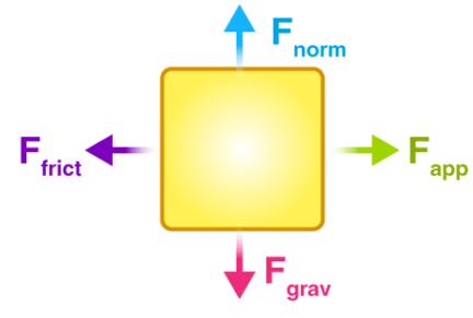
The free-body diagram above depicts four forces acting upon the object. Objects do not necessarily always have four forces acting upon them. There will be cases in which the number of forces depicted by a free-body diagram will be one, two, or three. There is no hard and fast rule about the number of forces that must be drawn in a free-body diagram. The only rule for drawing free-body diagrams is to depict all the forces that exist for that object in the given situation. Thus, to construct free body diagrams, it is extremely important to know the various types of forces.
Types of Forces
A force is a push or pull acting upon an object as a result of its interaction with another object. they are divided into contact and non-contact forces.
Contact Forces
- Frictional Force
- Tension Force
- Normal Force
- Air Resistance Force
- Applied Force
- Spring Force
Action-at-a-Distance Forces
- Gravitational Force
- Electrical Force
- Magnetic Force
Applied Force \(\mathrm{F}_{\mathrm{app}}\):
An applied force is a force that is applied to an object by a person or another object. If a person is pushing a desk across the room, then there is an applied force acting upon the object. The applied force is the force exerted on the desk by the person.
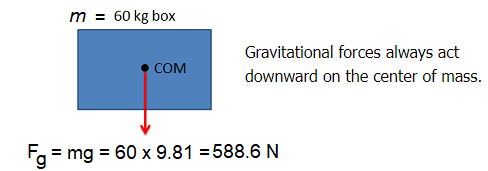
Gravity Force (also known as weight) \(\mathrm{F}_{\text {grav }}\):
The force of gravity is the force with which the earth, moon, or other massively large object attracts another object towards itself. By definition, this is the weight of the object. All objects upon earth experience a force of gravity that is directed “downward” towards the center of the earth. The force of gravity on earth is always equal to the weight of the object as found by the equation:
\(
\begin{gathered}
\text { Fgrav }=\mathrm{m} \times \mathrm{~g} \\
\text { where } \mathrm{g}=9.8 \mathrm{~N} / \mathrm{kg} \text { (on Earth) } \\
\text { and } \mathrm{m}=\text { mass (in } \mathrm{kg} \text { ) }
\end{gathered}
\)
Normal Force or Reaction force \(\mathrm{F}_{\text {norm }}\):
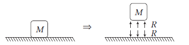
The normal force is the support force exerted upon an object that is in contact with another stable object. For example, if a book is resting upon a surface, then the surface is exerting an upward force upon the book in order to support the weight of the book. On occasions, a normal force is exerted horizontally between two objects that are in contact with each other. For instance, if a person leans against a wall, the wall pushes horizontally on the person.
Normal forces always act perpendicular to the surfaces in contact. The barrel in the hand truck shown on the left has a normal force at each contact point.
Friction Force \(F_{\text {frict }}\): The friction force is the force exerted by a surface as an object moves across it or makes an effort to move across it. There are at least two types of friction force – sliding and static friction. Though it is not always the case, the friction force often opposes the motion of an object. For example, if a book slides across the surface of a desk, then the desk exerts a friction force in the opposite direction of its motion. Friction results from the two surfaces being pressed together closely, causing intermolecular attractive forces between molecules of different surfaces. As such, friction depends upon the nature of the two surfaces and upon the degree to which they are pressed together. The maximum amount of friction force that a surface can exert upon an object can be calculated using the formula below:
\(
F_{\text {frict }}=\mu \times F_{\text {norm }}
\)
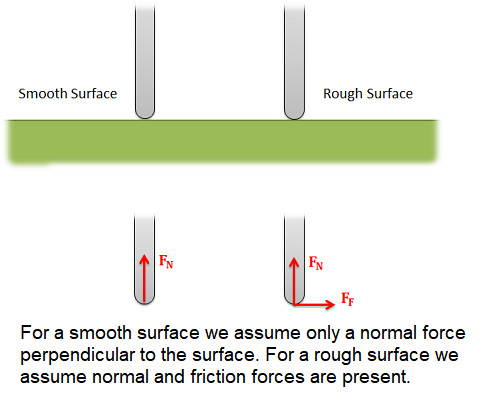
- For smooth surfaces we assume that there is no friction force.
- For rough surfaces we assume that the bodies will not slide relative to one another, no matter what. In this case, the friction force is always just large enough to prevent this sliding.
Air resistance Force \(\mathrm{F}_{\text {air }}\):
The air resistance is a special type of frictional force that acts upon objects as they travel through the air. The force of air resistance is often observed to oppose the motion of an object. This force will frequently be neglected due to its negligible magnitude (and due to the fact that it is mathematically difficult to predict its value). It is most noticeable for objects that travel at high speeds (e.g., a skydiver or a downhill skier) or for objects with large surface areas.
Tension Force \(F_{\text {tens }}\):
The tension force is the force that is transmitted through a string, rope, cable or wire when it is pulled tight by forces acting from opposite ends. The tension force is directed along the length of the wire and pulls equally on the objects on the opposite ends of the wire.
Cables, wires or ropes attached to the body will exert a tension force on the body in the direction of the cable. These forces will always pull on the body, as ropes, cables and other flexible tethers cannot be used for pushing.

Spring Force \(\mathrm{F}_{\text {spring }}\):
The spring force is the force exerted by a compressed or stretched spring upon any object that is attached to it. An object that compresses or stretches a spring is always acted upon by a force that restores the object to its rest or equilibrium position. For most springs (specifically, for those that are said to obey “Hooke’s Law”), the magnitude of the force is directly proportional to the amount of stretch or compression of the spring.
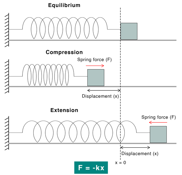
The spring force can be quantified using Hooke’s law. According to this law, when a spring stresses or compresses, the restoring force \(F\) is proportional to the displacement \(x\).
\(F \propto x\)
Spring Force Formula:
\(F=-k x\) (k is a spring constant)
The negative sign is because the force is opposite to the displacement, that is, the force displaces the spring from its equilibrium position. This equation applies to both compression and extension of spring.
The magnitude of the spring constant is given by,
\(
k=F / X
\)
Suppose \(F=1 \mathrm{~N}\) and \(x=1 \mathrm{~m}\), then
\(
k=1 \mathrm{~N} / 1 \mathrm{~m}=1 \mathrm{~N} / \mathrm{m}
\)
The spring constant is defined as the force required to displace the spring by one meter. It has a unit of Newton per meter \((\mathrm{N} / \mathrm{m})\) and a dimension given by \(\mathrm{MT}^{-2}\).
Some of the common forces that we come across in mechanics are described below:
Weight (w)
The weight of an object is equal to the gravitational force with which the earth pulls it downwards.
Weight of an object, \(w=m g\)
where, \(m=\) mass of the object and \(g=\) acceleration due to gravity.
Normal reaction ( \(R\) or \(N\) )
It is a contact force between two surfaces in contact, which is always perpendicular to the surfaces in contact. The following diagrams show normal reaction between two surfaces.
Block pushes ground downward with force \(R\) and ground pushes the block back with force \(R\), where \(R=\) normal reaction force. Three cases are shown below.
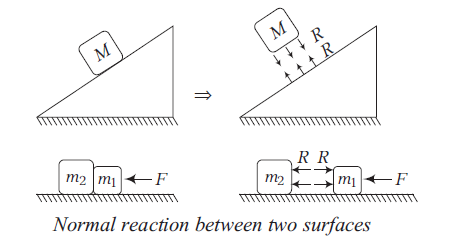
Here, \(m_1\) pushes \(m_2\) towards left by force \(R\) and \(m_2\) pushes \(m_1\) towards right by force \(R\). Normal force acts at both directions due to newtons third law, where each force has an equal and opposite reaction force.
Tension (T)
All physical objects that are in contact can exert forces on each other. We give these contact forces different names based on the types of objects in contact. If one of the objects exerting the force happens to be a rope, string, chain, or cable we call the force tension.
Regarding tension and string, the following points are important to remember
- Force of tension acts on a body in the direction away from the point of contact or tied ends of the string.
- If a string is inextensible, the magnitude of acceleration of any number of masses connected through string is always same.
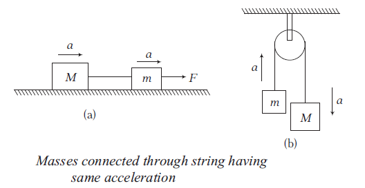
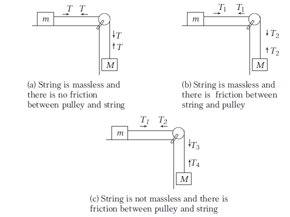
- If a string is massless, the tension in it is same everywhere. However, if a string has a mass, tension at different points will be different.
- If there is friction between string and pulley, tension is different on two sides of the pulley, but if there is no friction between pulley and string, tension will be same on both sides of the pulley.
These points can be understood in diagram as follows
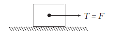
- If a force is directly applied on the string, the tension will be equal to the applied force irrespective of the motion of the pulling agent.
Free Body Diagram (FBD)
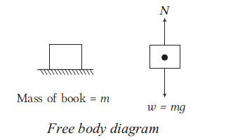
A free body diagram (FBD) consists of a diagrammatic representation of a single body or a sub-system of bodies isolated from its surroundings showing all the forces acting on it.
Consider, for example, a book lying on a horizontal surface as shown below. A free body diagram of the book alone would consist of its weight \((w=m g)\), acting through the centre of gravity and the reaction \((N)\) exerted on the book by the surface.
How to Make a Free Body Diagram (FBD)?
In this section, we will explain the step-by-step procedure of drawing a free body diagram: You can draw a free-body diagram of an object following these 3 steps:
- Sketch what is happening
- Determine the forces that act on the object
- Draw the object in isolation with the forces that act on it
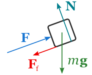
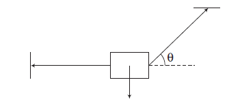
Example 1: A box is pushed up an incline with friction which makes an angle of \(20^{\circ}\) with the horizontal. Let’s draw the free-body diagram of the box.
Solution: Step-1: The first step is to sketch what is happening:
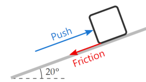
Step-2: The next step is to look at the sketch, and enumerate all the forces to which the box is subject:
- the upward push, \(\mathbf{F}\)
- the force of friction, \(\mathbf{F}_{\mathrm{f}}\)
- the normal force, \(\mathbf{N}\)
- and the force of gravity, \(m \mathbf{g}\)
Step-3: The final step is to draw the box with the 4 forces that act on it:
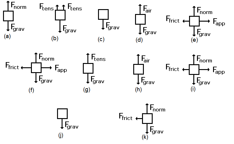
Example 2: (a) A book is at rest on a tabletop. Diagram the forces acting on the book
(b) A gymnast holding onto a bar, is suspended motionless in mid-air. The bar is supported by two ropes that attach to the ceiling. Diagram the forces acting on the combination of gymnast and bar.
(c) An egg is free-falling from a nest in a tree. Neglect air resistance. Diagram the forces acting on the egg as it is falling.
(d) A flying squirrel is gliding (no wing flaps) from a tree to the ground at constant velocity. Consider air resistance. Diagram the forces acting on the squirrel.
(e) A rightward force is applied to a book in order to move it across a desk with a rightward acceleration. Consider frictional forces. Neglect air resistance. Diagram the forces acting on the book.
(f) A rightward force is applied to a book in order to move it across a desk at constant velocity. Consider frictional forces. Neglect air resistance. Diagram the forces acting on the book.
(g) A college student rests a backpack upon his shoulder. The pack is suspended motionless by one strap from one shoulder. Diagram the vertical forces acting on the backpack.
(h) A skydiver is descending with a constant velocity. Consider air resistance. Diagram the forces acting upon the skydiver.
(i) A force is applied to the right to drag a sled across loosely packed snow with a rightward acceleration. Neglect air resistance. Diagram the forces acting upon the sled.
(j) A football is moving upwards towards its peak after having been booted by the punter. Neglect air resistance. Diagram the forces acting upon the football as it rises upward towards its peak.
(k) A car is coasting to the right and slowing down. Neglect air resistance. Diagram the forces acting upon the car.
Solution: FBD for each question drawn in the figure below.
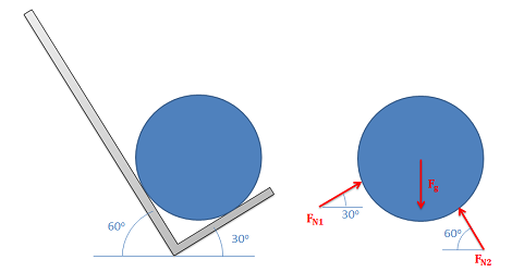
Example 3: A cylinder of weight \(w\) is resting on a \(V\)-groove as shown in figure. Draw its free body diagram.

Solution: The free body diagram of the cylinder is as shown in figure.
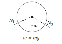
Here, \(w=\) weight of cylinder and \(N_1\) and \(N_2\) are the normal reactions between the cylinder and the two inclined walls.
Example 4: Three blocks A, B and C are placed one over the other as shown in figure. Draw free body diagrams of all the three blocks.
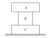
Solution: Free body diagrams of A, B and C are shown below.
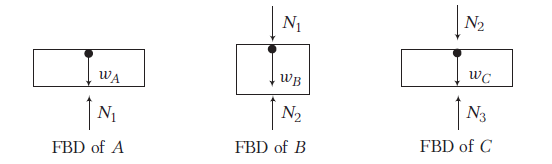
Here, \(N_1=\) normal reaction between \(A\) and \(B\),
\(N_2=\) normal reaction between \(B\) and \(C\)
and \(\quad N_3=\) normal reaction between \(C\) and ground.
Example 5: A block of mass \(m\) is attached with two strings as shown in figure. Draw the free body diagram of the block.
Solution: The free body diagram of the block is as shown in figure.
Example 6: All surfaces are smooth in following figure. Find F such that block remains stationary with respect to wedge.
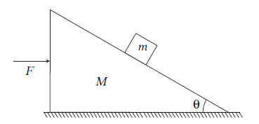
Solution: Acceleration of (block + wedge), \(a=\frac{F}{(M+m)}\)
From inertial frame of reference (ground) FBD of block (only real forces) with respect to ground, which is moving with an acceleration a is shown below. Horizontal direction: The horizontal component of the normal force ( \(N \sin \theta\) ) must balance the pseudo force (\(ma\)) acting on the block in the opposite direction of the wedge’s motion.
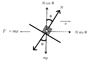
Since there is No vertical acceleration, \(a=0\)
\(
\Sigma F_y=0
\)
\(
N \cos \theta=m g \dots(i)
\)
\(
N \sin \theta=m a \dots(ii)
\)
From Eqs. (i) and (ii), we get
\(
\begin{array}{rlrl}
a & =g \tan \theta \\
\therefore \quad & F =(M+m) a=(M+m) g \tan \theta
\end{array}
\)
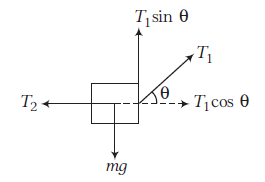
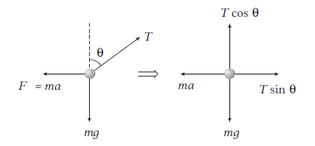
Example 7: A bob of mass \(m\) is suspended from the ceiling of a train moving with an acceleration a as shown in figure. Find the angle \(\theta\) in equilibrium position.
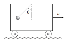
Solution: FBD of the problem is shown below.
As, with respect to train, bob is in equilibrium.
\(
\begin{array}{rlrlrl}
& \therefore & \Sigma F_x =0 \dots(i) \\
\Rightarrow & T \sin \theta =m a \\
& \therefore & \Sigma F_y =0 \dots(ii) \\
\Rightarrow & T \cos \theta =m g
\end{array}
\)
From Eqns. (i) and (ii), we get the same result, i.e.
\(
\theta=\tan ^{-1}\left(\frac{a}{g}\right)
\)
Note: The problem is analyzed from the non-inertial frame of reference of the accelerating train. In this frame, a pseudo-force (or inertial force) must be included. The pseudo-force, \(ma\), acts opposite to the direction of the train’s acceleration, so it is directed horizontally backward.
Apparent weight of a man in a lift
Let us consider a man of mass \(m\) is standing on a weighing machine placed in an elevator/lift. The actual weight \(m g\) of the man acts on the weighing machine and offers a reaction \(R\) given by the reading of the weighing machine. This reaction \(R\) exerted by the surface of contact on the man is apparent weight of the person.
Now, we consider how \(R\) is related to \(m g\) in the different conditions.
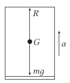
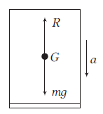
Case-I: When the lift moves upwards with acceleration \(a\) as shown in figure, the net upward force on the man is
\(
R-m g=m a \Rightarrow R=m a+m g
\)
Apparent weight, \(R=m(g+a)\)
So, when a lift accelerates upwards, the apparent weight of the man inside it increases.
Case-II: When the lift moves downwards with acceleration \(a\) as shown in figure, the net downward force on the man is
\(
\begin{aligned}
m g-R =m a \\
\text { Apparent weight, } R =m(g-a)
\end{aligned}
\)
So, when a lift accelerates downwards, the apparent weight of the man inside it decreases.
Case-III: When the lift is at rest or moving with uniform velocity \({v}\) downward or upward as shown in figure.
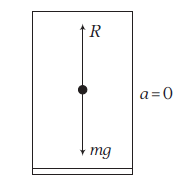
Then, acceleration \(a=0\). So, net force on the man is
\(
\begin{array}{rlrl}
R-m g & =m \times 0 \\
\Rightarrow R =m g \\
\text { or Apparent weight } & =\text { Actual weight }
\end{array}
\)
So, when the lift is at rest, the apparent weight of the man is his actual weight.
Case-IV: When the lift falls freely under gravity, if the supporting cable of the lift breaks. Then, \(a=g\).
The net downward force on the man is
\(
R=m(g-g) \Rightarrow R=0
\)
Thus, the apparent weight of the man becomes zero. This is because both the lift and man are moving downwards with the same acceleration \(g\) and so there is no force of action and reaction existing between the man and lift. Hence, a person develops a feeling of weightlessness when the lift falls freely under gravity.
Example 8: A spring balance is attached to the ceiling of an elevator. A boy hangs his bag on the spring and the spring reads \(49 \mathrm{~N}\), when the elevator is stationary. If the elevator moves downward with an acceleration of \(5 \mathrm{~ms}^{-2}\), what will be the reading of the spring balance?
Solution: When the elevator is stationary, then
\(
\begin{array}{rlrl}
& w =m g \\
\Rightarrow & 49 =m \times 9.8 \\
\Rightarrow & m =\frac{49}{9.8}=5 \mathrm{~kg}
\end{array}
\)
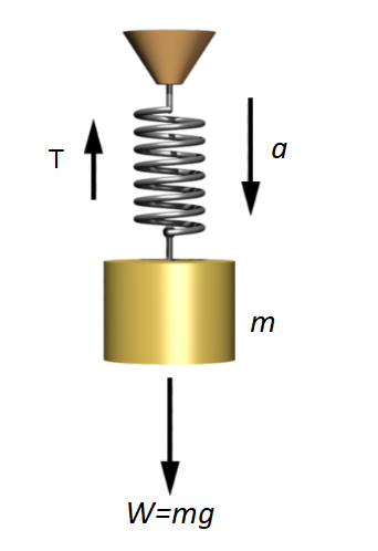
When the elevator is moving downward with an acceleration,
\(
m a=m g-T
\)
\(
\begin{aligned}
\Rightarrow T =m g-m a \\
=m(g-a)
\end{aligned}
\)
\(
T=m(9.8-a)=5(9.8-5)=24 \mathrm{~N}
\)
Example 9: If in a stationary elevator, a man is standing with a bucket full of water. The bucket has a hole at its bottom. The rate of flow of water through this hole is \(R_0\). If the elevator starts to move up and then down with same acceleration, then the rate of flow of water are \(R_u\) and \(R_d\). Find the relation between \(R_0, R_u\) and \(R_d\).
Solution: Rate of flow will be more when elevator will move in upward direction with some acceleration because the net downward pull will be more and vice-versa.
\(
\begin{array}{l}
F_{\text {upward }}=R_u=m(g+a) \\
F_{\text {downward }}=R_d=m(g-a) \\
\Rightarrow \quad F_{\text {at rest }}=R_0=m g \\
\end{array}
\)
Thus, relation between \(R_u, R_0\) and \(R_d\) is \(R_u>R_0>R_d\).
Example 10: In the adjoining figure, a wedge is fixed to an elevator moving upwards with an acceleration a. A block of mass \(m\) is placed over the wedge. Find the acceleration of the block with respect to wedge. Neglect friction.
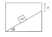
Solution: Since, acceleration of block w.r.t. wedge (an accelerating or non-inertial frame of reference) is to be find out. FBD of block w.r.t. wedge is shown in figure.
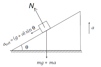
The acceleration would had been \(g \sin \theta\) (down the plane), if the lift were stationary or when only weight (i.e. \(\mathrm{mg}\) ) acts downwards.
Here, downward force is \(m(g+a)\)
\(\therefore\) Acceleration of the block (of course w.r.t. wedge) will be \((g+a) \sin \theta\) down the plane.
Applications Of Newton’s Laws Of Motion
Consider two bodies of masses \(m_1\) and \(m_2\) placed in direct contact with each other on a smooth platform.
Suppose a horizontal force is applied and both the bodies moves with acceleration \(a\), then
\(
F=\left(m_1+m_2\right) a
\)
Now, we can calculate normal reaction bet|ween the bodies, using free body diagram (FBD).
FBD of 1st body
\(\therefore \quad F-N=m_1 a \quad\) (From Newton’s 2nd law)
FBD of 2nd body
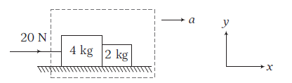
Example 11: Two blocks of masses \(4 \mathrm{~kg}\) and \(2 \mathrm{~kg}\) are placed side-by-side on a smooth horizontal surface as shown in the figure. A horizontal force of \(20 \mathrm{~N}\) is applied on \(4 \mathrm{~kg}\) block.
Find
(i) the acceleration of each block
(ii) and the normal reaction between two blocks.
Solution: (i) Since, both the blocks will move with same acceleration (say a) in horizontal direction. Let us take both the blocks as a system. Net external force on the system is \(20 \mathrm{~N}\) in horizontal direction.
Using
\(
\begin{array}{l}
\quad \begin{aligned}
\Sigma F_x & =m a_x \\
20 & =(4+2) a=6 a \text { or } a=\frac{10}{3} \mathrm{~ms}^{-2}
\end{aligned}
\end{array}
\)
(ii) The free body diagram of both the blocks are shown in the figure.
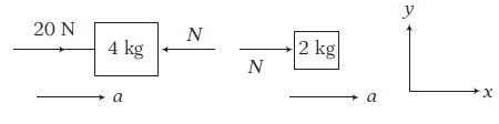
Using \(\quad \Sigma F_x=m a_x\)
For \(4 \mathrm{~kg}\) block, \(20-N=4 a=4 \times \frac{10}{3}\)
\(
\Rightarrow \quad N=20-\frac{40}{3}=\frac{20}{3} \mathrm{~N}
\)
For \(2 \mathrm{~kg}\) block, \(N=2 a=2 \times \frac{10}{3}=\frac{20}{3} \mathrm{~N}\)
Here, \(N\) is the normal reaction between the two blocks.
Note: In free body diagram of the blocks, we have not shown the forces acting on the blocks in vertical direction, because normal reaction between the blocks and acceleration of the system can be obtained without using \(\Sigma F_y=0\).
Example 12: Three blocks of masses \(3 \mathrm{~kg}, 2 \mathrm{~kg}\) and \(1 \mathrm{~kg}\) are placed side-by-side on a smooth surface as shown in figure. A horizontal force of \(12 \mathrm{~N}\) is applied on \(3 \mathrm{~kg}\) block. Find the net force on \(2 \mathrm{~kg}\) block.
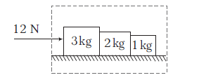
Solution: All the blocks will move with same acceleration (say a) in horizontal direction. Let us take all the blocks as a system, net external force on the system is \(12 \mathrm{~N}\) in horizontal direction.
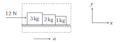
Using \(\Sigma F_x=m a_x\), we get
\(
12=(3+2+1) a=6 a \text { or } a=\frac{12}{6}=2 \mathrm{~ms}^{-2}
\)
Now, let \(F\) be the net force on \(2 \mathrm{~kg}\) block in \(x\)-direction, then using \(\Sigma F_x=m a_x\) for \(2 \mathrm{~kg}\) block, we get
\(
F=(2)(2)=4 \mathrm{~N}
\)
Note: Here, net force \(F\) on \(2 \mathrm{~kg}\) block is the resultant of \(N_1\) and \(N_2\left(N_1>N_2\right)\), where \(N_1=\) normal reaction between \(3 \mathrm{~kg}\) and \(2 \mathrm{~kg}\) block and \(N_2=\) normal reaction between \(2 \mathrm{~kg}\) and \(1 \mathrm{~kg}\) block. Thus, \(F=N_1-N_2\).
Motion of bodies connected through strings or springs
Horizontal motion
When two bodies are connected through an inextensible weightless string and a force is applied to impart an acceleration \(a\) in both the bodies, as given in the figure below, then equation of motion from the FBD can be given by
For \(A\),
\(T=m_1 a \dots(i)\)
For \(B\),
\(F-T=m_2 a \dots(ii)\)
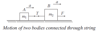
From Eqs. (i) and (ii), \(F=m_1 a+m_2 a \dots(iii)\)
From Eqns. (i) and (iii), \(T=\frac{m_1 F}{\left(m_1+m_2\right)}\)
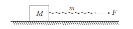
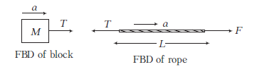
Example 13: A block of mass \(M\) is pulled along a horizontal frictionless surface by a rope of mass \(m\) as shown in figure. A horizontal force \(F\) is applied to one end of the rope. Find (i) the acceleration of the rope and block, (ii) the force that the rope exerts on the block (iii) and tension in the rope at its mid-point.
Solution: (i) Acceleration, \(a=\frac{F}{(m+M)}\)
(ii) Force exerted by rope on the block is
\(
T=M a=\frac{M \cdot F}{(m+M)}
\)
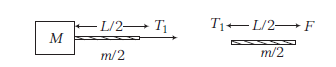
(iii) \(T_1=\left(\frac{m}{2}+M\right) a=\left(\frac{m+2 M}{2}\right)\left(\frac{F}{m+M}\right)\)
Tension in rope at mid-point, \(T_1=\frac{(m+2 M) F}{2(m+M)}\)
Example 14: In the arrangement shown in the figure, the strings are light and inextensible. The surface over which blocks are placed is smooth. Find
(i) the acceleration of each block
(ii) the tension in each string.
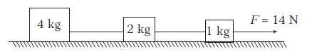
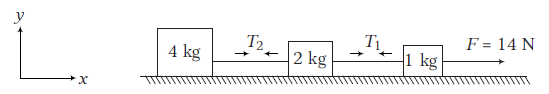
Solution: (i) Let \(a\) be the acceleration of each block and \(T_1\) and \(T_2\) be the tensions, in the two strings as shown in the figure.
Taking the three blocks and the two strings as the system.
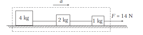
\begin{array}{l}
\text { Using } \quad \Sigma F_x=m a_x \\
\text { or } \quad 14=(4+2+1) a \text { or } a=\frac{14}{7}=2 \mathrm{~ms}^{-2} \\
\end{array}
\)
(ii) Free body diagram (showing the forces in \(x\)-direction only) of \(4 \mathrm{~kg}\) block and \(1 \mathrm{~kg}\) block are shown in figure.
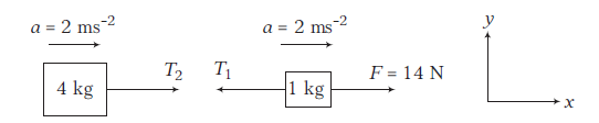
Using \(\Sigma F_x=m a_x\)
For \(1 \mathrm{~kg}\) block, \(\quad F-T_1=(1)(a)\) or \(14-T_1=(1)(2)=2\)
\(\therefore \quad T_1=14-2=12 \mathrm{~N}\)
For \(4 \mathrm{~kg}\) block, \(\quad T_2=(4)(a)\)
\(\therefore \quad T_2=(4)(2)=8 \mathrm{~N}\)
Vertical motion
In the same manner, as discussed above, we can calculate acceleration, tension in the string and common force in two or more blocks in vertical direction also.
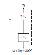
Example 15: The blocks of masses \(2 \mathrm{~kg}, 3 \mathrm{~kg}\) and \(5 \mathrm{~kg}\) are connected by light, inextensible strings as shown in figure.
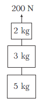
The system of blocks is raised vertically upwards by applying a force \(F_0=200 \mathrm{~N}\). Find the common acceleration and tension in the strings.
Solution:
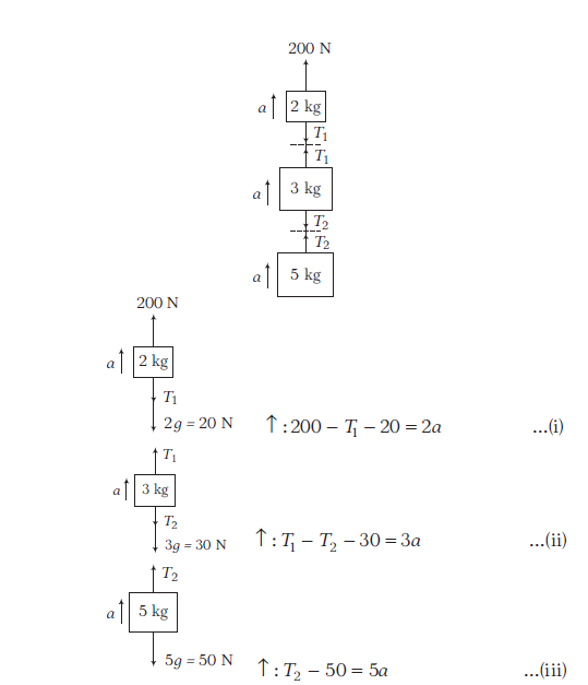
Adding Eqns. (i), (ii) and (iii), we get
\(
\begin{aligned}
100 & =10 a \quad \Rightarrow a=10 \mathrm{~ms}^{-2} \\
T_1 & =160 \mathrm{~N} \text { and } T_2=100 \mathrm{~N}
\end{aligned}
\)
Alternate Method: Taking three blocks together as a system
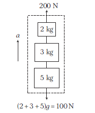
\begin{array}{c}
\uparrow: 200-100=(2+3+5) a \\
a=10 \mathrm{~ms}^{-2}
\end{array}
\)
Taking two blocks at a time
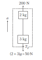
\begin{aligned}
200-50-T_2 & =(2+3) a \\
150-T_2 & =5 \times 10 \\
\Rightarrow \quad T_2 & =100 \mathrm{~N}
\end{aligned}
\)
\begin{aligned}
T_1-80 & =(3+5) a \\
T_1-80 & =8 \times 10 \\
T_1 & =160 \mathrm{~N}
\end{aligned}
\)
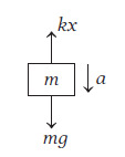
For spring-block system
In the same manner, as discussed above, we can calculate the tension in a spring connected to a block of mass \(m\), which produces an extension \(x\) in it, i.e. \(T=k x\).
where, \(k=\) spring constant.
Example 16: Two masses are connected to two identical springs of spring constant \(100 \mathrm{~N} / \mathrm{m}\) as shown in figure. Find the extension in both the springs.
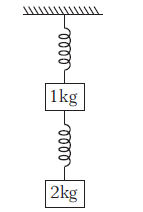
Solution: The FBD for mass \(2 \mathrm{~kg}\),
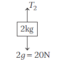
\(\Rightarrow \quad T_2-20=0\) or \(T_2=20 \mathrm{~N} \dots(i)\)
The FBD for mass \(1 \mathrm{~kg}\),
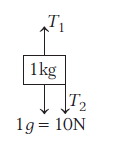
\(
\Rightarrow \quad T_1=T_2+10 \Rightarrow T_1=30 \mathrm{~N} \quad \text { [Using Eq. (i)] }
\)
As, these tensions in the springs are the spring forces,
\(
\begin{array}{ll}
\therefore & T_1=k x_1 \Rightarrow 30=100 \times x_1 \text { or } x_1=0.3 \mathrm{~m} \\
\text { and } & T_2=k x_2 \Rightarrow 20=100 \times x_2 \text { or } x_2=0.2 \mathrm{~m}
\end{array}
\)
Bodies attached through pulley (using strings or springs )
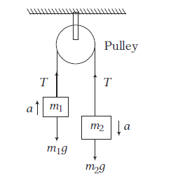
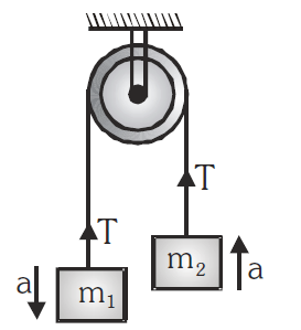
Case I: Consider two bodies of masses \(m_1\) and \(m_2\left(m_2>m_1\right)\) connected to a massless and inextensible string which passes through a smooth pulley. If they are allowed to move freely, they move with common acceleration \(a\). The tension in the string due to mass \(m_1\) and \(m_2\) is \(T\).
From FBD,
For \(A, \quad T-m_1 g=m_1 a \dots(i)\)
For \(B, \quad m_2 g-T=m_2 a \dots(ii)\)
On solving Eqs. (i) and (ii), we get
\(
\begin{aligned}
\Rightarrow & a=\frac{\left(m_2-m_1\right)}{\left(m_2+m_1\right)} g \\
\Rightarrow & T=\left(\frac{2 m_1 m_2}{m_1+m_2}\right) g
\end{aligned}
\)
Reaction at suspension of pulley \(R=2 T\).
Example 17: Two blocks of masses \(2.6 \mathrm{~kg}\) and \(4.1 \mathrm{~kg}\) are tied together by a light string looped over a frictionless pulley.
(a) What will the acceleration of each mass be?
(b) Find the value of tension in the string.
Solution: Here, \(m_1=2.6 \mathrm{~kg}, m_2=4.1 \mathrm{~kg}\)
FBD for \(m_1\),
\(
\begin{aligned}
T-m_1 g & =m_1 a \text { (upward) }\\
T-2.6 g & =2.6 a \dots(i)
\end{aligned}
\)
FBD for \(m_2\),
\(
\begin{array}{l}
m_2 g-T=m_2 a \text { (downward) }\\
4.1 g-T=4.1 a \dots(ii)
\end{array}
\)
(a) Adding Eqs. (i) and (ii), we get
\(
\begin{aligned}
4.1 g-2.6 g & =(2.6+4.1) a \\
\Rightarrow \quad a & =\frac{1.5 g}{6.7}=\frac{1.5 \times 10}{6.7} \\
& =2.2 \mathrm{~ms}^{-2}
\end{aligned}
\)
(b) Putting the value of \(a\) in Eq. (i), we get
\(
T-2.6 g=2.6 \times 2.2
\)
\(
\begin{aligned}
T & =2.6 \times 2.2+2.6 \times 10 \\
& =31.72 \mathrm{~N}
\end{aligned}
\)
Example 18: The pulley is light and smooth; the strings are inextensible and light. The system is released from rest. Find the acceleration of each block, tensions in the strings and reaction on pulley.

Solution:
Solving Eqs. (i), (ii) and (iii), we get
\(
a=6 \mathrm{~ms}^{-2}, T_1=20 \mathrm{~N}, T_2=32 \mathrm{~N}
\)
Forces on pulley, \(R-2 T_2=0\)
(Pulley is massless)
\(
R=2 T_2=64 \mathrm{~N}
\)
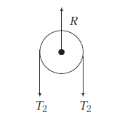
where, \(R\) is the reaction on the pulley.
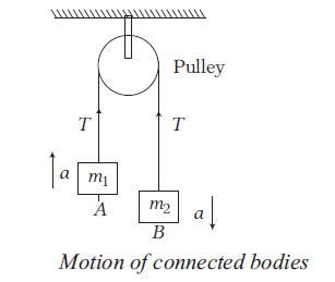
Case II: When two bodies are attached through a pulley as given in the figure below.
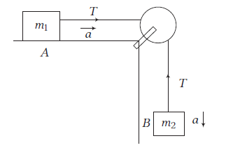
Here, \(m_2>m_1\), then from FBD,
For \(A, \quad T=m_1 a \dots(i)\)
For \(B, \quad m_2 a=m_2 g-T \dots(ii)\)
Solving Eqs. (i) and (ii), we get
\(
\begin{aligned}
a & =\frac{m_2}{\left(m_1+m_2\right)} g \\
\Rightarrow \quad T & =\frac{m_1 m_2}{\left(m_1+m_2\right)} g
\end{aligned}
\)
Example 19: A \(2 \mathrm{~kg}\) mass placed on a level table is attached to a \(5 \mathrm{~kg}\) mass by a string passing over the edge of a table as illustrated in the diagram.
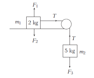
(a) Calculate the magnitude of acceleration of the system.
(b) Calculate the tension in the string.
Solution: From FBD in \(m_1\),
\(
\begin{aligned}
T-m_1 a & =0 \\
\Rightarrow \quad T-2 a & =0 \dots(i)
\end{aligned}
\)
FBD in \(m_2\),
\(
\begin{array}{c}
m_2 g-T=m_2 a \\
5 g-T=5 a
\end{array}
\)
Putting \(T=2 a\) from Eq. (i), we get
\(
\begin{array}{r}
5 g-2 a=5 a \\
7 a=5 g
\end{array}
\)
(a) \(a=\frac{5}{7} \times 10=\frac{50}{7} \mathrm{~ms}^{-2}\)
(b) Again, tension in the string,
\(
T=2 a=2 \times \frac{50}{7}=\frac{100}{7} \mathrm{~N}
\)
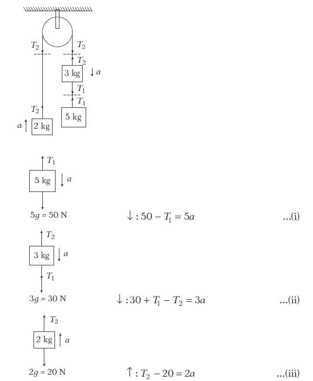
Example 20: The strings are inextensible and light; the pulleys are smooth and light. Find the acceleration of each block and tensions in the strings.
Solution:
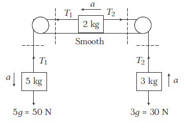
\(
5 \mathrm{~kg}: \quad \downarrow: 50-T_1=5 a \dots(i)
\)
\(
2 \mathrm{~kg}: \quad \leftarrow: T_1-T_2=2 a \dots(ii)
\)
\(
3 \mathrm{~kg}: \quad \uparrow: T_2-30=3 a \dots(iii)
\)
Adding Eqs. (i), (ii) and (iii), we get
\(
\begin{array}{l}
20=10 a \Rightarrow a=2 \mathrm{~ms}^{-2} \\
T_1=40 \mathrm{~N} \text { and } T_2=36 \mathrm{~N}
\end{array}
\)
Example 21: Consider the situation shown in figure. Initially the spring is unstretched when the block of mass is released from rest. Assume the pulley frictionless and light, the spring and string massless. Find the maximum extension of the spring.
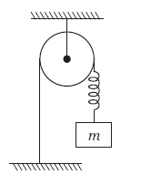
Solution:
The FBD of given mass \(m\)
\(
\begin{aligned}
m g-k x & =m a \text { or } a=g-\frac{k}{m} x \\
v d v & =\left(g-\frac{k}{m} x\right) d x
\end{aligned}
\)
Integrating both sides, we get or
\(
\begin{aligned}
\int_0^v v d v & =\int_0^x\left(g-\frac{k}{m} x\right) d x \Rightarrow \frac{v^2}{2}=g x-\frac{k x^2}{2 m} \\
v & =\left(2 g x-\frac{k x^2}{m}\right)^{1 / 2}
\end{aligned}
\)
When the block will stop, \(v=0\) (at maximum extension),
\(
\left(2 g x-\frac{k x^2}{m}\right)^{1 / 2}=0 \Rightarrow 2 g x=\frac{k x^2}{m} \Rightarrow x=x_m=\frac{2 m g}{k}
\)
Case III: When pulley is attached to the edge of an inclined plane To understand this case, first of all we need to understand the motion of an object placed on a frictionless inclined plane.
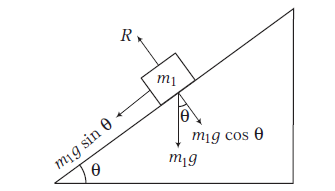
Consider an object of mass \(m_1\) is placed on a smooth inclined plane with angle of inclination \(\theta\). From the FBD of object, different forces acting on it, are
(i) Normal reaction \(R\), acting perpendicular to the plane.
(ii) Component of weight \(m_1 g \cos \theta\), acting perpendicular to plane.
(iii) Component of weight \(m_1 g \sin \theta\) downward along the inclined plane.
Here, \(R\) and \(m_1 g \cos \theta\) will cancel each other (as here is no motion in vertically upward and vertical downward direction), so these forces can be ignored.
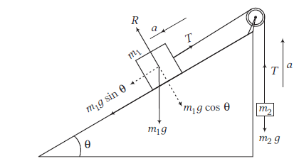
Now, a pulley is connected at the edge of inclined plane and a block of mass \(m_2\left(m_1>m_2\right)\) is connected through a string passing over the pulley to mass \(m_1\) as shown in Figure above.
Now, equation of motion for \(m_2\),
\(
T-m_2 g=m_2 a \dots(i)
\)
Equation of motion for \(m_1\),
\(
m_1 g \sin \theta-T=m_1 a \dots(ii)
\)
From Eqs. (i) and (ii), we get
\(
a=\frac{\left(m_1 g \sin \theta-m_2 g\right)}{\left(m_1+m_2\right)}
\)
\(
T=\frac{m_1 m_2}{m_1+m_2}(1+\sin \theta) g
\)
Example 22: Consider the situation shown in the figure. The surface is smooth and the string and the pulley are light. Find the acceleration of each block and tension in the string.
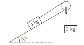
Solution:
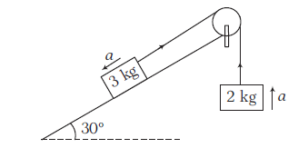
Let \(3 \mathrm{~kg}\) block be moving downward.
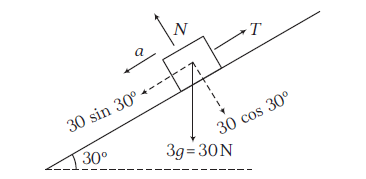
Along the plane: \(30 \sin 30^{\circ}-T=3 a \dots(i)\)
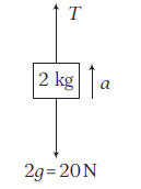
\(
T-20=2 a \dots(ii)
\)
Adding Eqs. (i) and (ii), we get
\(
a=-1 \mathrm{~ms}^{-2} \Rightarrow T=18 \mathrm{~N}
\)
Since, the acceleration is negative, i.e. the block of mass \(3 \mathrm{~kg}\) is moving upward.
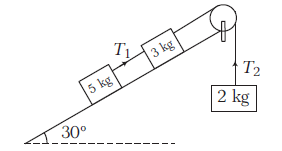
Example 23: In the arrangement shown, inclined plane is smooth, strings and pulleys are massless. Find \(\frac{T_1}{T_2}\).
Solution:
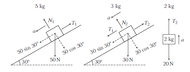
\(5 \mathrm{~kg}\) : along the plane : \(50 \sin 30^{\circ}-T_1=5 a \dots(i)\)
\(3 \mathrm{~kg}\) : along the plane : \(30 \sin 30^{\circ}+T_1-T_2=3 a \dots(ii)\)
\(2 \mathrm{~kg}: \uparrow: T_2-20=2 a \dots(iii)\)
Adding Eqs. (i), (ii) and (iii), we get
\(
\begin{array}{rlrl}
20 & =10 a \Rightarrow a=2 \mathrm{~ms}^{-2} \\
T_1 & =15 \mathrm{~N} \text { and } T_2=24 \mathrm{~N} \\
\therefore \quad & \frac{T_1}{T_2}=\frac{15}{24}=\frac{5}{8}
\end{array}
\)
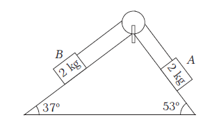
Example 24: In the arrangement shown, all the surfaces are smooth, strings and pulleys are light. Find the tension in the string.
Solution:
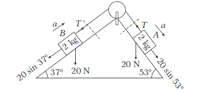
Block \(A\) : along the plane, \(20 \sin 53^{\circ}-T=2 a \dots(i)\)
Block \(B\) : along the plane, \(T-20 \sin 37^{\circ}=2 a \dots(ii)\)
Adding Eqs. (i) and (ii), we get
\(
\begin{array}{l}
20\left(\sin 53^{\circ}-\sin 37^{\circ}\right)=4 a \\
20\left(\frac{4}{5}-\frac{3}{5}\right)=4=4 a \Rightarrow a=1 \mathrm{~ms}^{-2} \\
T=20 \sin 37^{\circ}+2 a=20 \times \frac{3}{5}+2 \times 1=14 \mathrm{~N}
\end{array}
\)
Example 25: In the adjacent figure, masses of \(A, B\) and \(C\) are \(1 \mathrm{~kg}, 3 \mathrm{~kg}\) and \(2 \mathrm{~kg}\), respectively. Find
(i) the acceleration of the system
(ii) and tension in the string.
Neglect friction. \(\left(g=10 \mathrm{~ms}^{-2}\right)\)
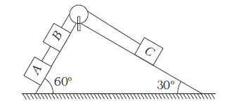
Solution: (i) In this case, net pulling force
\(
\begin{array}{l}
=m_A g \sin 60^{\circ}+m_B g \sin 60^{\circ}-m_C g \sin 30^{\circ} \\
=(1)(10)\left(\frac{\sqrt{3}}{2}\right)+(3)(10)\left(\frac{\sqrt{3}}{2}\right)-(2)(10)\left(\frac{1}{2}\right) \\
=24.64 \mathrm{~N}
\end{array}
\)
Total mass being pulled \(=1+3+2=6 \mathrm{~kg}\)
\(\therefore\) Acceleration of the system, \(a=\frac{24.64}{6}=4.10 \mathrm{~ms}^{-2}\)
(ii) For the tension in the string between \(A\) and \(B\)
FBD of A
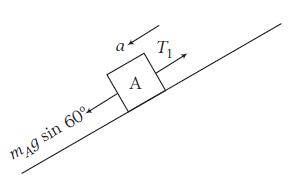
\(
\begin{array}{l}
m_A g \sin 60^{\circ}-T_1=\left(m_A\right)(a) \\
T_1=m_A g \sin 60^{\circ}-m_A a \\
\quad=m_A\left(g \sin 60^{\circ}-a\right) \\
T_1=(1)\left(10 \times \frac{\sqrt{3}}{2}-4.10\right)=4.56 \mathrm{~N}
\end{array}
\)
For the tension in the string between \(B\) and \(C\)
FBD of C
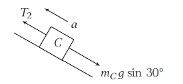
\begin{array}{l}
T_2-m_C g \sin 30^{\circ}=\left(m_C\right)(a) \\
T_2=m_C\left(a+g \sin 30^{\circ}\right) \\
T_2=2\left[4.10+10\left(\frac{1}{2}\right)\right]=18.2 \mathrm{~N}
\end{array}
\)
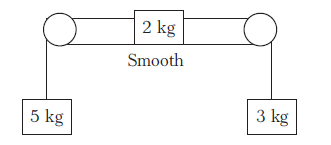
Example 26: Calculate the net acceleration produced in the arrangements shown below.
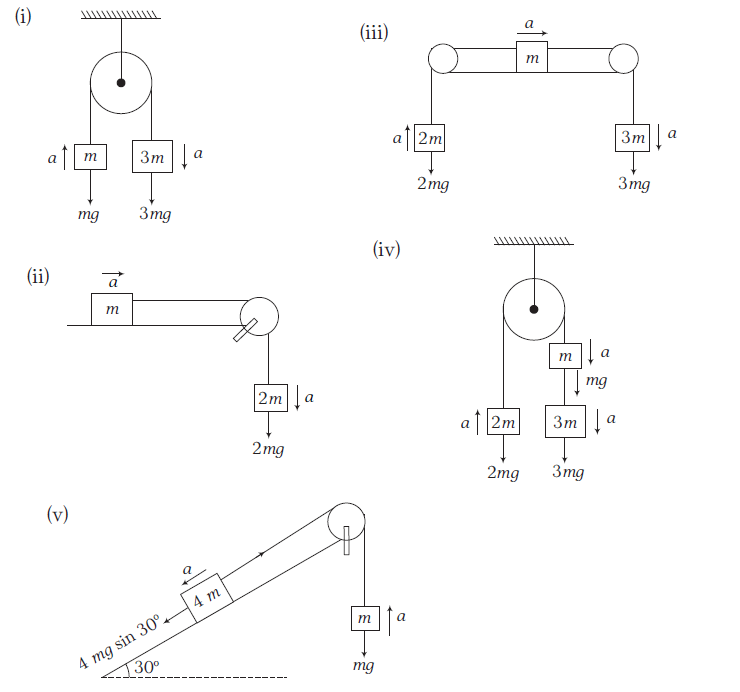
Solution:
\(
\begin{array}{l}
\text { (i) Net pulling force }=3 m g-m g=2 m g \\
\text { Total mass }=3 m+m=4 m \\
\qquad a=\frac{2 m g}{4 m}=\frac{g}{2}
\end{array}
\)
\(
\begin{array}{l}
\text { (ii) Pulling force }=2 \mathrm{mg} \\
\text { Total mass }=3 \mathrm{~m} \\
a=\frac{2 m g}{3 m}=\frac{2 g}{3} \\
\end{array}
\)
(iii) Net pulling force \(=3 m g-2 m g=m g\)
\(
\begin{aligned}
\text { Total mass } & =3 m+m+2 m=6 m \\
a & =\frac{m g}{6 m}=\frac{g}{6}
\end{aligned}
\)
\(
\begin{array}{l}
\text { (iv) Net pulling force }=3 m g+m g-2 m g \\
=2 \mathrm{mg} \\
\text { Total mass }=3 m+m+2 m=6 m \\
a=\frac{2 m g}{6 m}=\frac{g}{3} \\
\text { (v) Net pulling force }=4 m g \sin 30^{\circ}-m g \\
=m g \\
\text { Total mass }=4 m+m=5 m \\
\Rightarrow \quad a=\frac{m g}{5 m}=\frac{g}{5} \\
\end{array}
\)
Example 27: Draw the free-body diagram of the box when it is pulled parallel to the horizontal surface.
Solution:
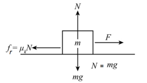
From the above figure, on balancing the forces, we get:
\(
\begin{aligned}
f_r & =F \\
\mu_k N & =F \quad(\therefore N=m g) \\
\mu_k m g & =F
\end{aligned}
\)
Example 28: Draw the free-body diagram of the box when it is pulled by a force at \(\theta=37^{\circ}\) above the horizontal surface.
Solution:
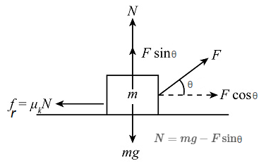
From the above figure, on balancing all the forces, we get:
\(
\begin{aligned}
f_r & =F \cos \theta=F \cos 37^{\circ} \\
\mu_k N & =F \cos \theta=F \cos 37^{\circ} \quad\left(\therefore N=m g-F \sin \theta=m g-F \sin 37^{\circ}\right) \\
\mu_k\left(m g-F \sin \theta\right) & =F \cos \theta \\
\mu_k\left(m g-F \sin 37^{\circ}\right) & =F \cos 37^{\circ}
\end{aligned}
\)
Example 29: Draw the free-body diagram of the box when it is pulled by a force at \(\theta\) above the horizontal surface.
Solution:
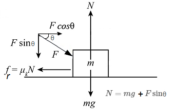
From the above figure, on balancing all the forces, we get:
\(
\begin{aligned}
f_r & =F \cos \theta \\
\mu_k N & =F \cos \theta \quad\left(\therefore N=m g+F \sin \theta\right) \\
\mu_k\left(m g+F \sin \theta\right) & =F \cos \theta \\
\end{aligned}
\)
Example 30: Draw the free body diagram of a body with mass \(m\) sliding down on an inclined plane.
Solution:
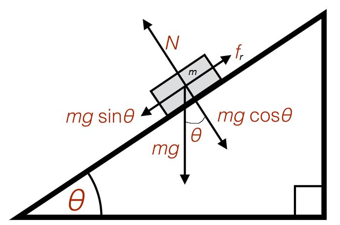
From the above figure, on balancing all the forces, we get:
\(N=m g \cos \theta\)
\(f_r=m g \sin \theta\)
Example 31: Draw the free body diagram of a body with mass \(m\) sliding down on an inclined plane shown below.
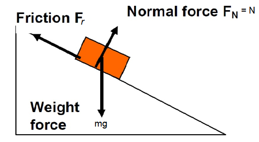
Solution: Weight Force acting on a block resolved into its components: Perpendicular and parallel to the incline. Remember that the normal force \(F_N\) is equal and opposite to the force exerted by the object on the plane \(m g \cos \theta\) (perpendicular to plane) otherwise it would fall through the plane, and \(m g \sin \theta\) (parallel to plane) forcing the object down the plane if no friction occurs.
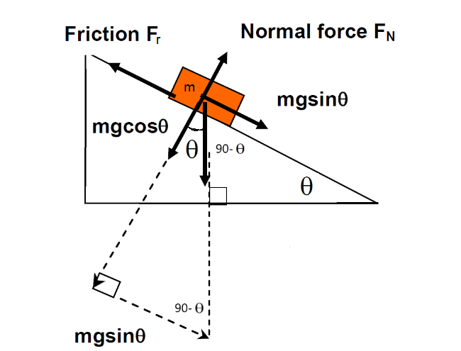
Note that with the above diagrams:
- Weight \(=m g\); acts through the centre of mass.
- Normal force \(F_N\) is always at right angles to the surface.
- Friction acts to oppose sliding motion (eg, if the mass were being dragged downhill, friction would act uphill)
- The weight force is resolved into 2 components:
- perpendicular to plane, and
- parallel to the plane.
- The resultant force \(\Sigma F\) down the slope is given by \(\Sigma F=m g \sin \theta-F_r\) where \(F_r\) is friction
- The resultant force \(\Sigma F\) perpendicular to the slope is zero (because it sits on the slope), hence: \(m g \cos \theta=F_N\)
Example 32: A toy car of mass \(50 \mathrm{~g}\) travels down a smooth incline at 30 degrees to the horizontal. Calculate:
(a) The net force acting on the car as it rolls down the slope, and
(b) The force of the incline on the car as it travels down the slope.
Friction may be ignored in this case.
\(
\text { Gravity }=9.8 \mathrm{~ms}^{-2} \text {. }
\)
Solution: Forces parallel to Slope:
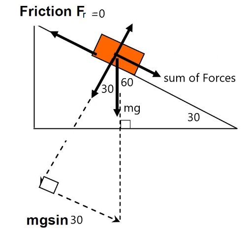
Note the angles: If slope is 30 degrees then \(90-30=60\) degrees in top corner then again \(90-60=30\) degrees from normal to vertical force so we would use \(m g \sin 30\) down the slope as the sum of all forces.
(a) As \(m g \sin \theta\) is the component of the force parallel to the slope then “sum of all forces” \(=\Sigma F\) :
\(
\begin{aligned}
\Sigma F & =m a \\
& =m g \sin \theta-F_r \\
& =m g \sin \theta-0 \\
& =m g \sin \theta
\end{aligned}
\)
Where \(m g \sin \theta\) is the component of the force parallel to the slope.
Note: the surface is friction-less (smooth) ie. \(F_r=0\), therefore the only force allowing the car to roll down the incline is the component of the gravitational force ‘ \(m g \sin \theta\) ‘.
\(
\begin{aligned}
\Sigma F & =m g \sin \theta \\
& =m \times g \times \sin \theta \\
& =50 \times 10^{-3} \times 9.8 \times \sin 30 \\
& =0.25 N
\end{aligned}
\)
Note: grams have been converted into kilograms
Forces perpendicular to slope:
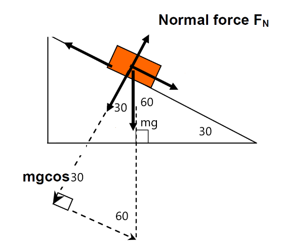
Also note the angles: If slope is 30 degrees then \(90-30=60\) degrees in top corner then again \(90-60=30\) degrees from normal to vertical force so we use \(m g \cos 30\) perpendicular to the slope as the normal force.
(b) The force of the incline on the car is a force that acts perpendicular to the slope, ie. the normal force \(F_N\) is equal to \(m g \cos \theta\)
\(
\begin{aligned}
F_N & =m g \cos \theta \\
& =m \times g \times \cos \theta \\
& =50 \times 10^{-3} \times 9.8 \times \cos 30 \\
& =0.43 N
\end{aligned}
\)
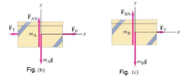
Example 33: Two boxes connected by a cord. Two boxes, A and B, are connected by a lightweight cord and are resting on a smooth (frictionless) table. The boxes have masses of \(12.0 \mathrm{~kg}\) and \(10.0 \mathrm{~kg}\). A horizontal force \(F_{\mathrm{P}}\) of \(40.0 \mathrm{~N}\) is applied to the \(10.0\mathrm{~kg}\) box, as shown in below. Find (a) the acceleration of each box, and
(b) the tension in the cord connecting the boxes.
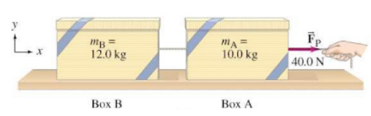
Solution: We streamline our approach by not listing each step. We have two boxes so we need to draw a free-body diagram for each box. To draw them correctly, we must consider the forces on each box by itself, so that Newton’s second law can be applied to each. The person exerts a force \(F_{\mathrm{P}}\) on box A. Box A exerts a force \(F_{\mathrm{T}}\) on the connecting cord, and the cord exerts an opposite but equal magnitude force \(F_{\mathrm{T}}\) back on box A (Newton’s third law). These two horizontal forces on box A are shown in Fig.b, along with the force of gravity \(m_{\mathrm{A}} \overrightarrow{\mathbf{g}}\) downward and the normal force \(\overrightarrow{\mathbf{F}}_{\mathrm{AN}}\) exerted upward by the table. The cord is light, so we neglect its mass. The tension at each end of the cord is thus the same. Hence the cord exerts a force \(F_{\mathrm{T}}\) on the second box. Figure c shows the forces on box B, which are \(\overrightarrow{\mathbf{F}}_{\mathrm{T}}, m_{\mathrm{B}} \overrightarrow{\mathbf{g}}\), and the normal force \(\overrightarrow{\mathbf{F}}_{\mathrm{BN}}\). There will be only horizontal motion. We take the positive \(x\) axis to the right.
(a) We apply \(\Sigma F_x=m a_x\) to box A:
\(
\Sigma F_x=F_{\mathrm{P}}-F_{\mathrm{T}}=m_{\mathrm{A}} a_{\mathrm{A}} \quad \text { [box A] }
\)
For box B, the only horizontal force is \(F_{\mathrm{T}}\), so
\(
\Sigma F_x=F_{\mathrm{T}}=m_{\mathrm{B}} a_{\mathrm{B}} \quad \text { [box B] }
\)
The boxes are connected, and if the cord remains taut and doesn’t stretch, then the two boxes will have the same acceleration \(a\). Thus \(a_{\mathrm{A}}=a_{\mathrm{B}}=a\). We are given \(m_{\mathrm{A}}=10.0 \mathrm{~kg}\) and \(m_{\mathrm{B}}=12.0 \mathrm{~kg}\). We can add the two equations above to eliminate an unknown \(\left(F_{\mathrm{T}}\right)\) and obtain
\(
\left(m_{\mathrm{A}}+m_{\mathrm{B}}\right) a=F_{\mathrm{P}}-F_{\mathrm{T}}+F_{\mathrm{T}}=F_{\mathrm{P}}
\)
or
\(
a=\frac{F_{\mathrm{P}}}{m_{\mathrm{A}}+m_{\mathrm{B}}}=\frac{40.0 \mathrm{~N}}{22.0 \mathrm{~kg}}=1.82 \mathrm{~m} / \mathrm{s}^2 .
\)
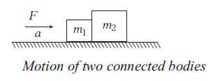
Motion of bodies in contact
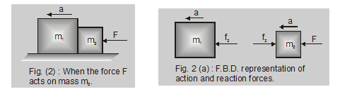
When the force \(F\) acts on the body with mass \(m_1\) as shown in fig. 1 and 1(a)
When two bodies of masses \(m_1\) and \(m_2\) are kept on the frictionless surface and a force \(\mathrm{F}\) is applied on one body, then the force with which one body presses the other at the point of contact is called force of contact. These two bodies will move with same acceleration a
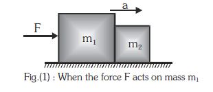
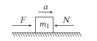
(i) When the force \(\mathrm{F}\) acts on the body with mass \(\mathrm{m}_1\) as shown in figure (1) : \(\mathrm{F}=\left(\mathrm{m}_1+\mathrm{m}_2\right) \mathrm{a}\)
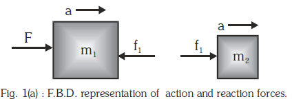
If the force exerted by \(\mathrm{m}_2\) on \(\mathrm{m}_1\) is \(\mathrm{f}_1\) (force of contact) then for body \(\mathrm{m}_1:\left(\mathrm{F}-\mathrm{f}_1\right)=\mathrm{m}_1 \mathrm{a}\)
\(
\begin{aligned}
&\mathrm{f}_1=\mathrm{F}-m_1 a\\
&=\left(m_1+m_2\right) a-m_1 a=m_2 a
\end{aligned}
\)
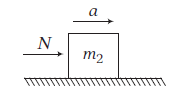
For body \(\mathrm{m}_2\) :
\(
\mathrm{f}_1=\mathrm{m}_2 \mathrm{a}
\)
\(\Rightarrow \text { action of } \mathrm{m}_1 \text { on } \mathrm{m}_2: \mathrm{f}_1=\frac{\mathrm{m}_2 \mathrm{~F}}{\mathrm{~m}_1+\mathrm{m}_2}\)
When the force \(\mathrm{F}\) acts on the body with mass \(m_2\) as shown in fig. 2 and 2(a)
\(
\mathrm{F}=\left(\mathrm{m}_1+\mathrm{m}_2\right) \mathrm{a}
\)
for body with mass \(m_2\)
\(
\mathrm{F}-\mathrm{f}_2=\mathrm{m}_2 \mathrm{a}
\)
\(
\begin{aligned}
& \mathrm{f}_2=\mathrm{F}-\mathrm{m}_2 \mathrm{a} \\
& =\left(m_1+m_2\right) a-m_2 a=m_1 a
\end{aligned}
\)
or action of \(\mathrm{m}_2\) on \(\mathrm{m}_1\)
\(
\mathrm{f}_2=\frac{\mathrm{m}_1 \mathrm{~F}}{\mathrm{~m}_1+\mathrm{m}_2}
\)
Three bodies of masses \(\mathrm{m}_1, \mathrm{~m}_2\) and \(\mathrm{m}_3\) placed one after another and in contact
Let us now consider three bodies of masses \(\mathrm{m}_1, \mathrm{~m}_2\) and \(\mathrm{m}_3\) placed one after another and in contact with each other. Suppose a force \(\mathrm{F}\) is applied horizontally on mass \(\mathrm{m}_1\)
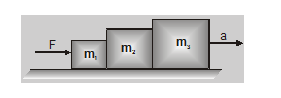
\(
\mathrm{F}-\mathrm{f}_1=\mathrm{m}_1 \mathrm{a}
\)
\(
f_1-f_2=m_2 a
\)
\(
\mathrm{f}_2=\mathrm{m}_3 \mathrm{a}
\)
Here \(\mathrm{F}=\left(\mathrm{m}_1+\mathrm{m}_2+\mathrm{m}_3\right) \mathrm{a}\)
\(
a=\frac{F}{\left(m_1+m_2+m_3\right)}
\)
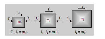
\(\mathrm{f}_1=\frac{\left(\mathrm{m}_2+\mathrm{m}_3\right) \mathrm{F}}{\left(\mathrm{m}_1+\mathrm{m}_2+\mathrm{m}_3\right)}\) (action on both \(\mathrm{m}_2\) and \(\mathrm{m}_3\) )
and \(f_2=\frac{m_3 F}{\left(m_1+m_2+m_3\right)} \text { (action on } \mathrm{m}_3 \text { alone) }\)
when the force \(\mathrm{F}\) is applied on \(m_3\), then
\(\mathrm{f}_1=\frac{\mathrm{m}_1 \mathrm{~F}}{\left(\mathrm{~m}_1+\mathrm{m}_2+\mathrm{m}_3\right)} \text { (action on } \mathrm{m}_1 \text { alone) }\)
and \(f_2=\frac{\left(m_1+m_2\right) F}{\left(m_1+m_2+m_3\right)} \text { (action on } \mathrm{m}_1 \text { and } \mathrm{m}_2 \text { ) }\)
Free Body Diagram of a Pulley System
A single fixed pulley changes the direction of force only and in general, an ideal pulley assumed to be massless and frictionless. A pulley has three arm during its motion.
- Central arm is known as main arm.
- Handing two arm are known as side arm.
- Main arm is fixed while side arms are free to move. In this case net force acting on ideal pulley will always be zero. Because \(F=m a\), for ideal pulley \(m=0\) and hence \(F=0\)
- If the tension in the two side string is equal to \(T\), the tension in the main string will be equal to \(2 T\).
- Say, if \(m_2>m_1\), Since the length of the string is fixed, so if \(m_2\) comes down by a distance \(x, m_1\) will go up by \(x\) only. Therefore, acceleration of both the blocks are equal in magnitude and opposite direction.
Note: If \(a\) comes out positive then assumed direction of \(a\) is correct. If \(a\) comes out negative, then actual direction is opposite to the direction assumed.

From free body diagram we get,
For mass \(m_1\) :
\(
T=m_1 a
\)
For mass \(m_2\) :
\(
m_2 g-T=m_2 a
\)
From these two equation we get,
\(
\text { Acceleration: } a=\frac{m_2}{\left(m_1+m_2\right)} g
\)
Tension of the string \(T=\frac{m_1 m_2}{\left(m_1+m_2\right)} g\)
Tension or thrust on pulley
\(
P=\sqrt{T^2+T^2}=\sqrt{2} T
\)
Inclined Pulley
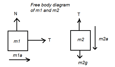
Case-I: Two masses are suspended over a pulley on a friction-less inclined plane as shown below in the figure. The mass \(m_2\) descends with an acceleration \(a\). The mass \(m_1\) is on inclined plane:

The free body diagram of the block with mass \(m_1\) and \(m_2\) are shown below.
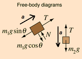
From free body diagram we get,
For mass \(m_1\) :
\(
T-m_1 g \sin \theta=m_1 a
\)
For mass \(m_2\) :
\(
m_2 g-T=m_2 a
\)
From these equation we get,
Acceleration \(a=\frac{\left(m_2-m_1 \sin \theta\right)}{\left(m_1+m_2\right)} g\) and,
Tension of the string \(T=\frac{m_1 m_2(1+\sin \theta)}{\left(m_1+m_2\right)} g\)
Example 34: A body of mass \(5 \mathrm{~kg}\) rests on a smooth plane inclined at an angle of \(35^{\circ}\) to the horizontal. It is connected by a light inextensible string passing over a smooth pulley fixed at the top of the plane, to another body of mass \(19 \mathrm{~kg}\) hanging freely vertically below the pulley. Given that the acceleration due to gravity \(g=9.8 \mathrm{~m} / \mathrm{s}^2\), determine the acceleration of the system.
Solution: The following figure shows the forces acting on the bodies and what the forces on the \(5 \mathrm{~kg}\) mass body due to its weight and the normal reaction on it sum to.
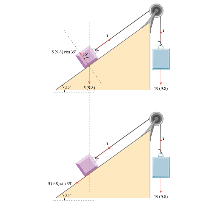
The accelerations of both bodies are equal. The acceleration of the \(19 \mathrm{~kg}\) mass body is given by
\(
a=\frac{\left(m_2 g\right)-T}{m_2}=\frac{19(9.8)-T}{19}=\frac{186.2-T}{19}
\)
\(
19 a=186.2-T \dots(1)
\)
The net force on the supported body can be expressed as
\(
F=T-\left(m_1 g \sin \theta\right)=T-\left(5(9.8) \sin 35^{\circ}\right)
\)
Force \(F\) can also be expressed as
\(
F=5 a
\)
Hence, we have
\(
5 a=T-\left(49 \sin 35^{\circ}\right) \dots(2)
\)
We now have two equations, (1) and (2), that can be added to give
\(
19 a+5 a=186.2-T+T-\left(49 \sin 35^{\circ}\right)
\)
This simplifies to
\(
\begin{aligned}
24 a & =186.2-\left(49 \sin \left(35^{\circ}\right)\right) \\
a & =\frac{186.2-\left(49 \sin \left(35^{\circ}\right)\right)}{24} .
\end{aligned}
\)
To two decimal places, this is \(6.59 \mathrm{~m} / \mathrm{s}^2\).
Case-II: When a body A of mass \(m_1\) rests on a horizontal surface with co-efficient of friction \(\mu\) between body and the table. Let a string passing over a pulley connect \(m_1\) with a body B of mass \(m_2\) as shown in below:

Free body diagram is shown below
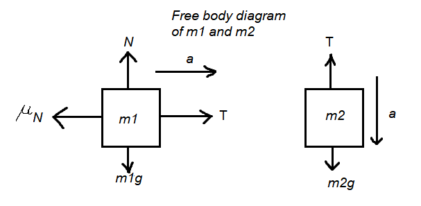
From free body diagram we get,
For mass \(m_1\) :
\(N=m_1 g\) and \(T-\mu N=m_1 a\)
or, \(T-\mu m_1 g=m_1 a\)
For mass \(m_2\) : \(m_2 g-T=m_2 a\)
From these two equation,
Acceleration \(a=\frac{\left(m_2-\mu m_1\right)}{\left(m_1+m_2\right)} g\)
and tension of the string \(T=\frac{m_1 m_2(1+\mu)}{\left(m_1+m_2\right)} g\)
Case-III: Two masses are suspended over a pulley on a inclined plane with coefficient of friction between the surface and the body is \(\mu\) as shown in figure below. The mass \(m_2\) descends with an acceleration \(a\). The mass \(m_1\) is on inclined plane:

Free body diagram is shown below:
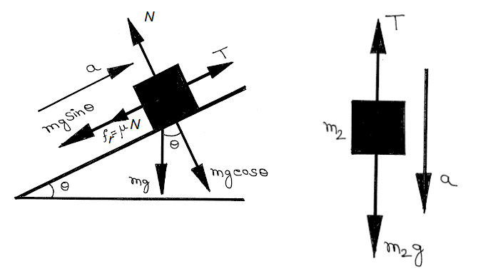
From free body diagram we get,
For mass \(m_1\) :
\(
N=m_1 g \cos \theta \text { and, } T-\mu N-m_1 g \sin \theta=m_1 a
\)
For mass \(m_2\) :
\(
m_2 g-T=m_2 a
\)
From these two equation we get,
Acceleration \(a=\frac{\left[m_2-m_1(\sin \theta+\mu \cos \theta)\right]}{\left(m_1+m_2\right)} g\) and,
Tension of the string \(T=\frac{m_1 m_2(1+\sin \theta+\mu \cos \theta)}{\left(m_1+m_2\right)} g\)
Case-IV: Two body \(\mathrm{A}\) and \(\mathrm{B}\) of masses \(m_1\) and \(m_2\) are connected by a string passing over a friction-less pulley such that \(m_2>m_1\) :

Free body diagram is shown below:

From free body diagram we get,
For mass \(m_1\) :
\(
T-m_1 g \sin \alpha=m_1 a
\)
For mass \(m_2\) :
\(
m_2 g \sin \beta-T=m_2 a
\)
From these two equations we get,
Acceleration \(a=\frac{\left(m_2 \sin \beta-m_1 \sin \alpha\right)}{\left(m_1+m_2\right)} g\) and,
Tension of the string \(T=\frac{m_1 m_2(\sin \alpha+\sin \beta)}{\left(m_1+m_2\right)} g\)
Case-V: The mass \(M\) is connected to \(m_1\) and \(m_2\) via string passing over alight pulleys. Let \(m_1>m_2\). Obviously \(m_1\) moves down an acceleration \(a\). The block on the horizontal table moves towards right with acceleration \(a:\)
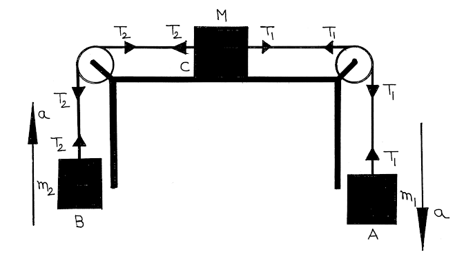
Free body Diagram is shown below:

From free body Diagram we get,
For mass \(m_1\) :
\(
m_1 g-T_1=m_1 a
\)
For mass \(m_2\) :
\(
T_2-m_2 g=m_2 a
\)
For mass \(M\) :
\(
T_1-T_2=M a
\)
From these equation we get,
Acceleration \(a=\frac{\left(m_1-m_2\right)}{\left(m_1+m_2+M\right)} g\) and,
Tension of the string \(T_1=\frac{m_1\left(2 m_2+M\right)}{\left(m_1+m_2+M\right)} g\) and,
Tension of the string \(T_2=\frac{m_2\left(2 m_1+M\right)}{\left(m_1+m_2+M\right)} g\)
Case-VI: Two body of masses \(m_1\) and \(m_2\) are connected by a string passing over a friction-less pulley such that \(m_1>m_2\) :
Now, we should be able to write the balancing forces acting on the body without drawing FBD.
Let \(\mathrm{m}_1>\mathrm{m}_2\) now for mass \(\mathrm{m}_1\):\(\mathrm{~m}_1 \mathrm{~g}-\mathrm{T}=\mathrm{m}_1 \mathrm{a}\)
for mass \(\mathrm{m}_2\):\(\mathrm{~T}-\mathrm{m}_2 \mathrm{~g}=\mathrm{m}_2 \mathrm{a}\)
\(
\text { Acceleration }=\mathrm{a}=\frac{\left(\mathrm{m}_1-\mathrm{m}_2\right)}{\left(\mathrm{m}_1+\mathrm{m}_2\right)} \mathrm{g}=\frac{\text { net pulling force }}{\text { total mass to be pulled }}
\)
\(
\text { Tension }=\mathrm{T}=\frac{2 \mathrm{~m}_1 \mathrm{~m}_2}{\left(\mathrm{~m}_1+\mathrm{m}_2\right)} \mathrm{g}=\frac{2 \times \text { Product of masses }}{\text { Sum of two masses }} \mathrm{g}
\)
Reaction at the suspension of pulley :
\(
\mathrm{R}=2 \mathrm{~T}=\frac{4 \mathrm{~m}_1 \mathrm{~m}_2 \mathrm{~g}}{\left(\mathrm{~m}_1+\mathrm{m}_2\right)}
\)
Case-VII: Blocks Hanging from multiple Pulleys
Pulleys (assume ideal pulley) get especially interesting in situations like the following example, where at least one of the pulleys is able to move. The two blocks remain at rest in the system of ropes and pulleys shown in the diagram. Given this information, can you conclude how the two masses compare?
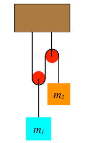
Lets draw the FBD
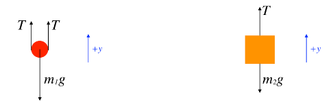
[We have taken the liberty of defining coordinate systems in our FBDs – up is the \(+y\)-direction for both – which we will need shortly.]
One might ask why there are two tension force vectors drawn for the pulley. The simplest answer is to consider what you would feel if you cut the rope on both sides of the pulley and held one end in each hand. Clearly you would feel both ends of the rope pulling down. Therefore by Newton’s third law, both ends of the rope are pulling up on the pulley. With the pulley massless and frictionless, these two tension forces must also be equal, which explains why they are labeled the same. Note that the tension vector on the block is also labeled with the same variable name. This is because it is the same rope, and our assumption of massless, frictionless pulleys ensures that everywhere that we measure the tension for a single piece of rope, it will be the same.
Another curious aspect of this FBD is the weight label of the left pulley. Technically, that force is acting on the block, and the block is pulling on the pulley. The pull on the pulley by the block happens to equal the weight of the block in this case, and the pulley has no weight of its own, so we are justified in taking this little shortcut. Another way to justify it is to treat the block + pulley as a single system, and the gravity force on the system is the force vector shown.
The next step in our analysis is to sum the forces for each object and apply Newton’s second law, which in this case involves zero acceleration. In taking the sum of forces, we have to take care to correctly use our coordinate system:
\(\left.\begin{array}{l}
0=a_1=\frac{F_{\text {net } 1}}{m_1}=\frac{2 T-m_1 g}{m_1} \quad \Rightarrow \quad T=\frac{m_1 g}{2} \\
0=a_2=\frac{F_{\text {net } 2}}{m_2}=\frac{T-m_2 g}{m_2} \Rightarrow T=m_2 g
\end{array}\right\} \Rightarrow m_1=2 m_2
\)
Notice that the light weight \(m_2\) holds up the heavier one because the placement of the pulley allows us to use the tension from the same rope twice on the heavier mass. This trick can actually be repeated as many times as we like (the pulley can have multiple tracks in it), and this enables us to lift very heavy weights with very little force. This invention is called a block and tackle. They are used for sailing ships (the heavy sails and boom can be pulled tighter), lifting engine blocks, and many other applications.
Example 35: The heights of the two blocks in the diagram below differ by \(36 \mathrm{~cm}\). When they are released from rest, the higher block falls while the lower block rises. One of the blocks has a mass that is three times the mass of the other block, the pulleys are massless and frictionless, and the string doesn’t stretch.
(a). Which is the heavier block? Explain.
(b). Find the distance that the lower block rises when the two blocks are aligned.
(c). Find the time it takes for the two blocks to be aligned.
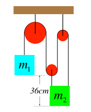
Solution: (a). The tension exerted by the string threaded through the pulleys is the same everywhere, so there is three times as much tension force acting up on the lower block as there is up on the higher one. If the lower block was three times heavier than the higher block, then the system would be balanced, and neither mass could be accelerating. [You should try doing the math of part (c) with the masses the other way, and demonstrate for yourself that it the acceleration would have to be zero.] Given that the system is accelerating, it must be the higher block with the greater mass.
(b). As the top block pulls the string down on one side of the large pulley, the same amount of string that is gained on the left side of the pulley is lost from the right side. The string on the right side of the large pulley is divided between the three segments holding up the other block. Therefore the lower block moves up one third as far as the higher block moves down. If the lower block rises a distance \(y\), then the higher block drops a distance \(3 y\), and since they reach the same height, the sum of those changes is \(36 \mathrm{~cm}\), which means the lower block rises a distance of \(y=9 \mathrm{~cm}\).
(c). To find the the time it takes them to align, we need to use their accelerations. We know their relative accelerations already: The lower block accelerates at one third the rate of the higher block. We’ll therefore call the higher block’s acceleration ” \(3 a\),” making the lower block’s acceleration equal to a. But we need Newton’s laws in order to go any further. FBD of the two systems involved look like this:
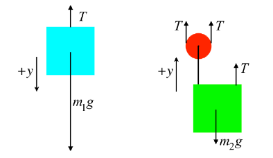
The higher mass is three times the lower mass, so we will call \(m_2\) simply ” \(m\),” which makes \(m_1\) equal to \(3 m\). Plugging everything into Newton’s second law for both FBDs gives these equations:
\(
\left.\begin{array}{lll}
a_1=\frac{F_{\text {net } 1}}{m_1} & \Rightarrow & 3 a=\frac{-T+3 m g}{3 m} \\
a_2=\frac{F_{\text {net } 2}}{m_2} & \Rightarrow & a=\frac{3 T-m g}{m}
\end{array}\right\} \Rightarrow a=\frac{2}{7} g
\)
With the acceleration of the lower block, the distance it travels, and the fact that it starts from rest, we can compute the time it takes to make the trip:
\(
y=v_o t+\frac{1}{2} a t^2 \Rightarrow t=\sqrt{\frac{7 y}{g}}=0.25 s
\)
Example 36: The system depicted in Figure below shows two blocks that remain at rest which are attached by a massless string over a massless, frictionless pulley, The plane is inclined at an angle theta up from the horizontal, and its surface is rough (i.e. not frictionless). The mass of the hanging block is given, as is the angle of incline and the coefficient of static friction. From these quantities, determine the minimum possible value of the mass of the block on the plane.
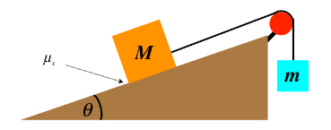
Solution: Starting (as always) with a FBD (including a coordinate system) for each block, we have:
Let’s take a moment to comment on the direction of the static friction force. Recall that a static friction force merely reacts to the “attempted” motion of the object along the surface. In this case, if the block was “trying” to slide down the plane, then the static friction force must be up the plane. Here it is drawn pointing down the plane, which means the other forces present must be such that they would accelerate it up the plane… How do we know this is the case? The answer lies in the statement of the question: We are looking for the minimum mass for the block on the plane. Imagine putting in a block whose mass balances the system. if a small mass is added to or subtracted from the block, the system may still remain at rest, as the static friction keeps the balance. If we add too much mass to that block, the static friction will reach its limit and the block will begin sliding down, while if we take away too much mass, it will slide up the plane. The static friction will oppose the intended motion, so for the minimum mass, the static friction force must point down the plane.
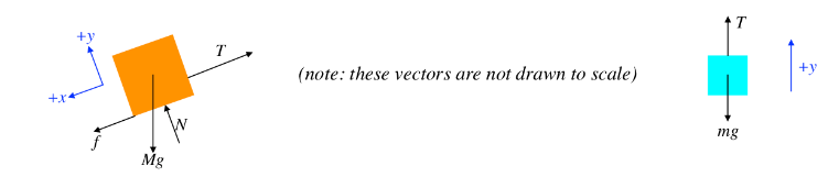
Breaking the vectors into components in our chosen coordinate systems and applying Newton’s second law (for zero acceleration) gives:
Block on plane :
\(x\)-direction forces \(: 0=a_x=\frac{f-T+M g \sin \theta}{M}\)
\(y-\) direction forces : \(0=a_y=\frac{N-M g \cos \theta}{M}\)
Hanging block: \(\quad y\)-direction forces : \(0=a_y=\frac{T-m g}{m}\)
Next, apply the constraint that relates the maximum static friction force (which occurs when the minimum mass is on the plane) and the normal force:
\(
\left.f \leq \mu_S N \Rightarrow \text { (maximum } f \text { for minimum } M\right) \Rightarrow f=\mu_S N
\)
The rest is algebra with four simultaneous equations, the result of which is:
\(
M_{\text {min }}=\frac{m}{\mu_S \cos \theta+\sin \theta}
\)
We should now check to see if this answer makes sense. If the angle theta is \(90^{\circ}\), then both masses are hanging, and there is not friction force (because there is no normal force). For the system not to accelerate, the two masses must be equal. Plugging in \(\theta=90^{\circ}\) indeed results in \(M=m\). The \(\theta=0^{\circ}\) case (a horizontal surface, where the normal force equals the weight of the block on the surface) will require that the friction force equals the weight of the hanging block. That is, we must have \(m g=f=\mu_S N=\mu_S M g \Rightarrow m=\mu_S M\), which is what we get when we plug in zero for \(\theta\).
Example 37: A rope is fastened to a \(50.0 \mathrm{~kg}\) block in two places and passes through a system of two pulleys, as shown in the diagram below. The block rests on a rough (coefficient of static friction is 0.400) horizontal surface. The bigger pulley is then pulled upward with gradually increasing force. Both pulleys are massless and frictionless, and the rope is also massless. The smaller pulley is fastened to the floor and the both pulleys are positioned such that the rope is perpendicular to the floor on one end and parallel to it on the other. When the pull force reaches a certain magnitude, the block just barely begins to slide to the right. Compute the magnitude of this pull force.
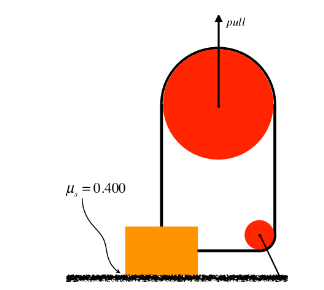
Solution: This problem is a good example of the importance of following the prescription listed above. Start with the free-body diagrams and coordinate systems. The FBD of the smaller pulley will yield us nothing useful, so there are just two FBDs to draw. Note that the tension on the side of the block comes from the same rope as the tension on the top of the block, so they are equal:
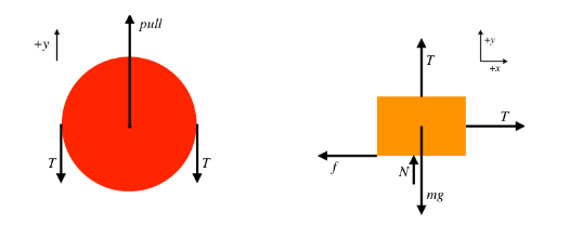
The block is not accelerating at all (nor is the pulley), so the sum of the forces in each of the \(x\) and \(y\) directions comes out to zero.
Block : \(\quad x\)-direction forces : \(0=T-f\)
\(y\)-direction forces : \(0=T+N-m g\)
Pulley: \(y\)-direction forces : \(0=\) pull \(-2 T\)
If we have to pull “just hard enough” to get the block moving, then this occurs when the horizontal pull equals the maximum static friction force, which gives us a constraint equation:
\(
f=\mu_S N
\)
Note that the block will have to start sliding before it starts rising, because rising requires than the normal force equals zero, and it will slide when the static friction force is small-but-non-zero. Now solve the equations simultaneously to get:
\(
\text { pull }=280 N
\)