NCERT Exercise Q & A
EXERCISE PROBLEMS
Q6.1: Predict the direction of induced current in the situations described by the following Figs. 6.15(a) to (f).

Answer: The direction of the induced current in a closed loop is given by Lenz’s law. The given pairs of figures show the direction of the induced current when the North pole of a bar magnet is moved towards and away from a closed loop respectively.

Using Lenz’s rule, the direction of the induced current in the given situations can be predicted as follows:
(a) The direction of the induced current is along \(\boldsymbol{qrpq}\).
(b) The direction of the induced current is along \(\boldsymbol{prqp}\).
(c) The direction of the induced current is along \(\boldsymbol{y} \boldsymbol{z x y}\).
(d) The direction of the induced current is along \(\boldsymbol{z y x z}\).
(e) The direction of the induced current is along \(\boldsymbol{x r y x}\).
(f) No current is induced since the field lines are lying in the plane of the closed loop.
Q6.2: Use Lenz’s law to determine the direction of induced current in the situations described by Fig. 6.16:
(a) A wire of irregular shape turning into a circular shape;
(b) A circular loop being deformed into a narrow straight wire.

Answer: (a) When a wire of irregular shape turns into a circular loop, area of the loop tends to increase. Therefore, magnetic flux linked with the loop increases. According to Lenz’s law, the direction of induced current must oppose the change in magnetic field, for which induced current should flow along adcba (anticlockwise).
(b) In this case, the magnetic flux tends to decrease. Therefore, induced current must support the magnetic field, for which induced current should flow along adcba (anticlockwise).
Q6.3: A long solenoid with 15 turns per cm has a small loop of area \(2.0 \mathrm{~cm}^2\) placed inside the solenoid normal to its axis. If the current carried by the solenoid changes steadily from 2.0 A to 4.0 A in 0.1 s , what is the induced emf in the loop while the current is changing?
Answer: Number of turns on the solenoid \(=15\) turns \(/ \mathrm{cm}=1500\) turns \(/ \mathrm{m}\)
Number of turns per unit length, \(n=1500\) turns
The solenoid has a small loop of area, \(A=2.0 \mathrm{~cm}^2=2 \times 10^{-4} \mathrm{~m}^2\)
Current carried by the solenoid changes from 2 A to 4 A .
\(\therefore\) Change in current in the solenoid, \(d i=4-2=2 \mathrm{~A}\)
Change in time, \(d t=0.1 \mathrm{~s}\)
Induced emf in the solenoid is given by Faraday’s law as:
\(
e=\frac{d \phi}{d t}
\)
Where, \(\phi=\) Induced flux through the small loop \(=B A \ldots(i i)\)
\(
\begin{aligned}
& B=\text { Maanetic field } \\
& =\mu_0 n i \dots(iii)
\end{aligned}
\)
\(\mu_0=\) Permeability of free space
\(
=4 \pi \times 10^{-7} \mathrm{H} / \mathrm{m}
\)
Hence, equation (i) reduces to:
\(
\begin{aligned}
e & =\frac{d}{d t}(B A) \\
& =A \mu_0 n \times\left(\frac{d i}{d t}\right) \\
& =2 \times 10^{-4} \times 4 \pi \times 10^{-7} \times 1500 \times \frac{2}{0.1} \\
& =7.54 \times 10^{-6} \mathrm{~V}
\end{aligned}
\)
Hence, the induced voltage in the loop is \(7.54 \times 10^{-6} \mathrm{~V}\).
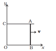
Q6.4: A rectangular wire loop of sides 8 cm and 2 cm with a small cut is moving out of a region of uniform magnetic field of magnitude 0.3 T directed normal to the loop. What is the emf developed across the cut if the velocity of the loop is \(1 \mathrm{~cm} \mathrm{~s}^{-1}\) in a direction normal to the (a) longer side, (b) shorter side of the loop? For how long does the induced voltage last in each case?
Answer: Length of the rectangular wire, \(l=8 \mathrm{~cm}=0.08 \mathrm{~m}\)
Width of the rectangular wire, \(b=2 \mathrm{~cm}=0.02 \mathrm{~m}\)
Hence, area of the rectangular loop,
\(
\begin{aligned}
& A=l b \\
& =0.08 \times 0.02 \\
& =16 \times 10^{-4} \mathrm{~m}^2
\end{aligned}
\)
Magnetic field strength, \(B=0.3 \mathrm{~T}\)
Velocity of the loop, \(v=1 \mathrm{~cm} / \mathrm{s}=0.01 \mathrm{~m} / \mathrm{s}\)
(a) Emf developed in the loop is given as:
\(
\begin{aligned}
& \mathrm{e}=B / V \\
& =0.3 \times 0.08 \times 0.01=2.4 \times 10^{-4} \mathrm{~V}
\end{aligned}
\)
Time taken to travel along the width, \(t=\frac{\text { Distance travelled }}{\text { Velocity }}=\frac{b}{v}\)
\(
=\frac{0.02}{0.01}=2 \mathrm{~s}
\)
Hence, the induced voltage is \(2.4 \times 10^{-4} \mathrm{~V}\) which lasts for 2 s .
(b) Emf developed, \(e=B b v\)
\(
=0.3 \times 0.02 \times 0.01=0.6 \times 10^{-4} \mathrm{~V}
\)
Time taken to travel along the length, \(t=\frac{\text { Distance traveled }}{\text { Velocity }}=\frac{l}{v}\)
\(
=\frac{0.08}{0.01}=8 \mathrm{~s}
\)
Hence, the induced voltage is \(0.6 \times 10^{-4} \mathrm{~V}\) which lasts for 8 s.
Q6.5: A 1.0 m long metallic rod is rotated with an angular frequency of \(400 \mathrm{~rad} \mathrm{~s}^{-1}\) about an axis normal to the rod passing through its one end. The other end of the rod is in contact with a circular metallic ring. A constant and uniform magnetic field of 0.5 T parallel to the axis exists everywhere. Calculate the emf developed between the centre and the ring.
Answer: Length of the rod, \(I=1 \mathrm{~m}\)
Angular frequency, \(\omega=400 \mathrm{rad} / \mathrm{s}\)
Magnetic field strength, \(B=0.5 \mathrm{~T}\)
One end of the rod has zero linear velocity, while the other end has a linear velocity of \(1 \omega\).
Average linear velocity of the rod,
\(
v=\frac{l \omega+0}{2}=\frac{l \omega}{2}
\)
Emf developed between the centre and the ring,
\(
\begin{aligned}
e & =B l v=B l\left(\frac{l \omega}{2}\right)=\frac{B l^2 \omega}{2} \\
& =\frac{0.5 \times(1)^2 \times 400}{2}=100 \mathrm{~V}
\end{aligned}
\)
Hence, the emf developed between the centre and the ring is 100 V.
Q6.6: A horizontal straight wire 10 m long extending from east to west is falling with a speed of \(5.0 \mathrm{~m} \mathrm{~s}^{-1}\), at right angles to the horizontal component of the earth’s magnetic field, \(0.30 \times 10^{-4} \mathrm{~Wb} \mathrm{~m}^{-2}\).
(a) What is the instantaneous value of the emf induced in the wire?
(b) What is the direction of the emf?
(c) Which end of the wire is at the higher electrical potential?
Answer: Length of the wire, \(l=10 \mathrm{~m}\)
Falling speed of the wire, \(v=5.0 \mathrm{~m} / \mathrm{s}\)
Magnetic field strength, \(B=0.3 \times 10^{-4} \mathrm{~Wb} \mathrm{~m}^{-2}\)
(a) Emf induced in the wire,
\(
\begin{aligned}
& e=B l v \\
& =0.3 \times 10^{-4} \times 5 \times 10 \\
& =1.5 \times 10^{-3} \mathrm{~V}
\end{aligned}
\)
(b) Using Fleming’s right hand rule, it can be inferred that the direction of the induced emf is from West to East.
(c) The eastern end of the wire is at a higher potential.
Q6.7: Current in a circuit falls from 5.0 A to 0.0 A in 0.1 s . If an average emf of 200 V induced, give an estimate of the self-inductance of the circuit.
Answer: Initial current, \(I_1=5.0 \mathrm{~A}\)
Final current, \(I_2=0.0 \mathrm{~A}\)
Change in current, \(d I=I_1-I_2=5 \mathrm{~A}\)
Time taken for the change, \(t=0.1 \mathrm{~s}\)
Average emf, \(e=200 \mathrm{~V}\)
For self-inductance ( \(L\) ) of the coil, we have the relation for average emf as:
\(
\begin{aligned}
e & =L \frac{d i}{d t} \\
L & =\frac{e}{\left(\frac{d i}{d t}\right)} \\
& =\frac{200}{\frac{5}{0.1}}=4 \mathrm{H}
\end{aligned}
\)
Hence, the self induction of the coil is 4 H.
Q6.8: A pair of adjacent coils has a mutual inductance of 1.5 H . If the current in one coil changes from 0 to 20 A in 0.5 s , what is the change of flux linkage with the other coil?
Answer: Mutual inductance of a pair of coils, \(\mu=1.5 \mathrm{H}\)
Initial current, \(I_1=0 \mathrm{~A}\)
Final current \(I_2=20 \mathrm{~A}\)
Change in current, \(d I=I_2-I_1=20-0=20 \mathrm{~A}\)
Time taken for the change, \(t=0.5 \mathrm{~s}\)
Induced emf, \(e=\frac{d \phi}{d t} \dots(1)\)
Where \(d \phi_{\text {is the change in the flux linkage with the coil. }}\)
Emf is related with mutual inductance as:
\(
e=\mu \frac{d I}{d t} \dots(2)
\)
Equating equations (1) and (2), we get
\(
\begin{aligned}
\frac{d \phi}{d t} & =\mu \frac{d I}{d t} \\
d \phi & =1.5 \times(20) \\
& =30 \mathrm{~Wb}
\end{aligned}
\)
Hence, the change in the flux linkage is 30 Wb.
Exemplar Problems
VSA
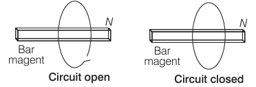
Q6.11: Consider a magnet surrounded by a wire with an on/off switch S (Figure below). If the switch is thrown from the off position (open circuit) to the on position (closed circuit), will a current flow in the circuit? Explain.
Answer: Concept: The magnetic flux linked with uniform surface of area A in uniform magnetic field is given by
\(
\phi=\mathbf{B} \cdot \mathbf{A}=B A \cos \theta
\)
So, flux linked will change only when either \(\vec{B}\), or A or the angle between \(\vec{B}\) and A change.
Whenever the number of magnetic lines of force (magnetic flux) passing through a circuit changes an emf is produced in the circuit called induced emf. The induced emf persists only as long as there is a change or cutting of flux. The induced emf is given by rate of change of magnetic flux linked with the circuit i.e, \(\varepsilon=-\mathrm{d} \Phi / \mathrm{dt}\). so flux linked will change when either magnetic field, area or the angle between \(\vec{B}\) and A (cross Section area) changes. If the switch is closed, the circuit will complete. But to induce emf in the circuit, we need:
(i) a changing magnetic field, but the bar magnet is stationary so it is not possible in this situation.
(ii) A changing area, which is also not possible because area is also constant as coil is not expanding or compressed.
(iii) Angle between \(\vec{B}\) and A changes, which is also not possible in this situation because orientation of bar magnet and coil is fixed.
Thus, no change in magnetic flux linked with coil occur, hence no electromotive force is produced and consequently no current will flow in the circuit.
Note:
\(
\begin{aligned}
& \phi=\vec{B} \cdot \vec{A}=\text { const } \\
& \varepsilon=-\frac{d \phi}{d t}=0 \\
& i=\frac{\varepsilon}{R}=0
\end{aligned}
\)
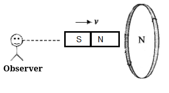
Q6.12: A wire in the form of a tightly wound solenoid is connected to a DC source, and carries a current. If the coil is stretched so that there are gaps between successive elements of the spiral coil, will the current increase or decrease? Explain.
Answer: Concept: Here, the application of Lenz’s law is tested through this problem. This law gives the direction of induced emf/induced current. According to this law, the direction of induced emf or current in a circuit is such as to oppose the cause that produces it. This law is based upon the law of conservation of energy.
(i) When AT-pole of a bar magnet moves towards the coil, the flux associated with the loop increases and an emf is induced in it. Since the circuit of loop is closed, induced current also flows in it.
(ii) Cause of this induced current is approach of north pole and therefore to oppose the cause, i.e., to repel the approaching north pole, the induced current in loop is in such a direction so that the front face of loop behaves as north pole. Therefore induced current as seen by observer O is in anticlockwise direction (figure).
When the coil is stretched so that there are gaps between successive elements of the spiral coil i.e., the wires are pulled apart which lead to the flux leak through the gaps. According to Lenz’s law, the emf produced must oppose this decrease, which can be done by an increase in current. So, the current will increase.
Q6.13: A solenoid is connected to a battery so that a steady current flows through it. If an iron core is inserted into the solenoid, will the current increase or decrease? Explain.
Answer: This problem is based on Lenz’s law and according to this law, the direction of induced emf or current in a circuit is such as to oppose the cause that produces it.

When the iron core is inserted in the current carrying solenoid, the magnetic field increases due to the magnetisation of iron core and hence the flux increases.
So, the emf induced in the coil must oppose this increase in flux, so the current induced in the coil in such a direction that it will oppose the increasing magnetic field which can be done by making decrease in current. So, the current will decrease.
Q6.14: Consider a metal ring kept on top of a fixed solenoid (say on a carboard) (Figure below). The centre of the ring coincides with the axis of the solenoid. If the current is suddenly switched on, the metal ring jumps up. Explain

Answer: This problem is based on Lenz’s law and according to this law, the direction of induced emf or current in a circuit is such as to oppose the cause that produces it. Initially there is no flux linked with the ring or we can say that initially flux through the ring is zero. When the switch is closed current start flowing in the circuit, magnetic flux is linked through the ring. Thus increase in flux takes place. According to Lenz’s law, this increase will be resisted and this can happen if the ring moves away from the solenoid.

This happen because the flux increases will cause an anticlockwise current (as seen from the top in the ring in figure.), i.e., opposite direction to that in the solenoid.
This makes the same sense of flow of current in the ring (when viewed from the bottom of the ring) and solenoid forming same magnetic pole in front of each other. Hence, they will repel each other and the ring will move upward.
Q6.15: Consider a metal ring kept (supported by a cardboard) on top of a fixed solenoid carrying a current \(I\) (Figure below). The centre of the ring coincides with the axis of the solenoid. If the current in the solenoid is switched off, what will happen to the ring?
Answer: This problem is based on Lenz’s law and according to this law, the direction of induced emf or current in a circuit is such as to oppose the cause that produces it.

When the switch is opened, current in the circuit of solenoid stops flowing. Initially there is some magnetic flux linked with the solenoid and now if current in the circuit stops, the magnetic flux falls to zero or we can say that magnetic flux linked through the ring decreases. According to Lenz’s law, this decrease in flux will be opposed and the ring experiences downward force towards the solenoid.
This happen because the current i decrease will cause a clockwise current (as seen from the top in the ring in figure) to increase the decreasing flux. This can be done if the direction of induced magnetic field is same as that of solenoid. This makes the opposite sense of flow of current in the ring (when viewed from the bottom of the ring) and solenoid forming opposite magnetic pole in front of each other. Hence, they will -attract each other but as ring is placed at the cardboard it could not be able to move downward.
Q6.16: Consider a metallic pipe with an inner radius of 1 cm . If a cylindrical bar magnet of radius 0.8 cm is dropped through the pipe, it takes more time to come down than it takes for a similar unmagnetised cylindrical iron bar dropped through the metallic pipe. Explain.
Answer: Key concept: Lenz’s Law.
This law gives the direction of induced emf/induced current. According to this law, the direction of induced emf or current in a circuit is such as to oppose the cause that produces it. This law is based upon the law of conservation of energy.
Eddy Current. When a changing magnetic flux is applied to a bulk piece of conducting material, then circulating currents called eddy currents are induced in the material. Because the resistance of the bulk conductor is usually low, eddy currents often have large magnitudes and heat up the conductor. When a cylindrical bar magnet is dropped through the metallic pipe flux linked with the cylinder changes and consequently eddy currents are produced in the metallic pipe. According to Lenz’s law, these currents will oppose the motion of the magnet, which is the cause of induction.
Therefore, magnet’s downward acceleration will be less than the acceleration due to gravity g . On the other hand, an un-magnetised iron bar will not produce eddy currents and will fall with acceleration due to gravity g. Thus, the magnet will take more time to come down than it takes for a similar un-magnetised cylindrical iron bar dropped through the metallic pipe, so, magnetised magnet takes more time.
SA (Short Answer Type)
Q6.17: A magnetic field in a certain region is given by \(\mathbf{B}=B_o \cos (\omega t) \hat{\mathbf{k}}\) and a coil of radius \(a\) with resistance \(R\) is placed in the \(x-y\) plane with its centre at the origin in the magnetic field (see Figure below) . Find the magnitude and the direction of the current at \((a, 0,0)\) at \(t=\pi / 2 \omega, t=\pi / \omega\) and \(t=3 \pi / 2 \omega\).

Answer: Key concept:
(1) First law: When ever the number of magnetic lines of force(magnetic flux) passing through a circuit changes, an emf is produced in the circuit called induced emf. The induced emf persists only as long as there is a change or cutting of flux.
(2) Second law : The induced emf is given by the rate of change of magnetic flux linked with the circuit, i.e. \(\varepsilon=-\frac{d \phi}{d t}\). For \(N\) turns \(\varepsilon=-\frac{N d \phi}{d t} ;\) Negative sign indicates that induced emf \((e)\) opposes the change of flux.
First we need to find out the flux passing through the ring at any instant and that is given by
\(
\phi_m=\vec{B} \cdot \vec{A}=B A \cos \theta
\)
And as we know both \(\vec{A}\) (àrea vector) and \(\vec{B}\) (magnetic field vector) are directed along \(z\)-axis. So, angle between them is 0.
\(
\begin{aligned}
& \text { So, } \cos \theta=1(\because \theta=0) \\
& \Rightarrow \quad \phi_m=B A
\end{aligned}
\)
Area of coil of radius \(a=\pi a^2\)
\(
\varepsilon=B_0\left(\pi a^2\right) \cos \omega t
\)
By Faraday’s law of electromagnetic induction, Magnitude of induced emf is given by
\(
\varepsilon=B_0\left(\pi a^2\right) \omega \sin \omega t
\)
This causes flow of induced current, which is given by
\(
I=\frac{B_0\left(\pi a^2\right) \omega \sin \omega t}{R}
\)
Now, the value of current at different instants,
(i)
\(
\begin{aligned}
& t=\frac{\pi}{2 \omega} \\
& I=\frac{B_0\left(\pi a^2\right) \omega}{R} \text { along } \hat{j}
\end{aligned}
\)
Because \(\sin \omega t=\sin \left(\omega \frac{\pi}{2 \omega}\right)=\sin \frac{\pi}{2}=1\)
(ii) \(t=\frac{\pi}{\omega}, I=\frac{B\left(\pi a^2\right) \omega}{R}=0\)
because, \(\sin \omega t=\sin \left(\omega \frac{\pi}{\omega}\right)=\sin \pi=0\)
(iii)
\(
\begin{aligned}
& t=\frac{3}{2} \frac{\pi}{\omega} \\
& I=\frac{B\left(\pi a^2\right) \omega}{R} \text { along }-\hat{j} \\
& \sin \omega t=\sin \left(\omega \cdot \frac{3 \pi}{2 \omega}\right)=\sin \frac{3 \pi}{2}=-1
\end{aligned}
\)
Q6.18: Consider a closed loop C in a magnetic field (Figure below). The flux passing through the loop is defined by choosing a surface whose edge coincides with the loop and using the formula \(\phi=\mathbf{B}_1 \cdot \boldsymbol{d} \mathbf{A}_1+\boldsymbol{B}_2 \cdot \boldsymbol{d} \mathbf{A}_2+\ldots\). Now if we chose two different surfaces \(\mathrm{S}_1\) and \(\mathrm{S}_2\) having C as their edge, would we get the same answer for flux. Jusity your answer.
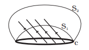
Answer: We would get the same answer for magnetic flux. Let us discuss its reason in detail. The magnetic flux linked with the surface can be considered as the number of magnetic field lines passing through the surface. So, let \(\mathrm{d} \Phi=\mathrm{B} . \mathrm{dA}\) represents magnetic lines in an area A to B . Magnetic field cannot end or start in space, this property of magnetic field lines based upon the concept of continuity. Therefore the number of lines passing through surface \(S_1\) must be the same as the number of lines passing through the surface \(\mathrm{S}_2\). Therefore, in both the cases we get the same magnetic flux.
Important point: Magnetic field lines can neither be originated nor be destroyed in space. This property is based on the concept of continuity.
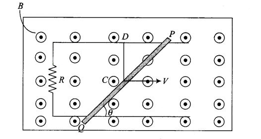
Q6.19: Find the current in the wire for the configuration shown in Figure below. Wire PQ has negligible resistance. \(\mathbf{B}\), the magnetic field is coming out of the paper. \(\theta\) is a fixed angle made by \(P Q\) travelling smoothly over two conducting parallel wires seperated by a distance \(d\).
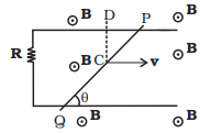
Answer: Key concept: This problem is based upon the motional emf.
Consider a conducting rod of length \(l\) moving with a uniform velocity \(\mathbf{v}\) perpendicular to a uniform magnetic field \(\mathbf{B}\), directed into the plane of the paper. Let the rod be moving to the right as shown in figure. The conducting electrons also move to the right as they are trapped within the rod.
Conducting electrons experience a magnetic force \(F_m=e v B\). So they move from \(P\) to \(Q\) within the rod. The end \(P\) of the rod becomes positively charged while end \(Q\) becomes negatively charged, hence an electric field is set up within the rod which opposes the further downward movement of electrons, i.e., an equilibrium is reached and in equilibrium \(F_e=F_m\), i.e.,
\(
e E=e v B \text { or } E=v B \Rightarrow \operatorname{Induced} \text { emf } e=E l=\boldsymbol{B v} l\left[E=\frac{V}{l}\right]
\)
If rod is moved by making an angle \(\theta\) with the direction of magnetic field or length. Induced emf,
\(
e=B v l \sin \theta
\)
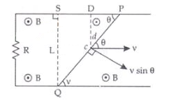
Emf induced across \(P Q\) due to its motion or change in magnetic flux linked with the loop change due to the change of enclosed area.
The induced electric field \(E\) along the dotted line \(C D\) (Perpendicular to both \(\vec{v}\) and \(\vec{B}\) and along \(\vec{v} \times \vec{B})=\nu B\)
Therefore, the motional emf along
\(
\begin{aligned}
P Q & =(\text { length } P Q) \times(\text { field along } P Q) \\
& =(\text { length } P Q) \times(v B \sin \theta) \\
& =\left(\frac{d}{\sin \theta}\right) \times(v B \sin \theta)=v B d
\end{aligned}
\)
This induced emf make flow of current in closed circuit of resistance \(R\).
\(I=\frac{d \nu B}{R}\) and is independent of \(\theta\).
Q6.20: A (current vs time) graph of the current passing through a solenoid is shown in Figure below. For which time is the back electromotive force (\(u\)) a maximum. If the back emf at \(t=3 \mathrm{~s}\) is \(e\), find the back emf at \(t=7 \mathrm{~s}, 15 \mathrm{~s}\) and \(40 \mathrm{~s} . \mathrm{OA}, \mathrm{AB}\) and BC are straight line segments.

Answer:Key concept: Whenever the electric current passing through a coil or circuit changes, the magnetic flux linked with it will also change. As a result of this, in accordance with’Faraday’s laws of electromagnetic induction, an emf is induced in the coil or the circuit which opposes the change that causes this induced emf is called back emf, the current so produced in the coil is called induced current. The induced emf is given by
\(
\begin{aligned}
& \varepsilon=-\frac{d\left(N \phi_B\right)}{d t} \\
& \varepsilon=-L \frac{d l}{d t}
\end{aligned}
\)
Thus, negative sign indicates that induced emf (\(e\) same as \(\varepsilon\)) opposes any change (increase or decrease) of current in the coil.
When the rate of change of current is maximum, then back emf in solenoid is ( \(u\) ) a maximum. This occurs in \(A B\) part of the graph. So maximum back emf will be obtained between \(5 \mathrm{~s}<t<10 \mathrm{~s}\).
Since, the back emf at \(t=3 \mathrm{~s}\) is \(e\).
Also, the rate of change of current at \(t=3\), and slope(s) of \(O A\) (from \(t=0 \mathrm{~s}\) to \(t=5 \mathrm{~s}\) ) \(=1 / 5 \mathrm{~A} / \mathrm{s}\).
So, we have
If \(u=L 1 / 5\left(\right.\) for \(\left.t=3 \mathrm{~s}, \frac{d I}{d t}=1 / 5\right)\).
where, \(L\) is a constant (coefficient of self-induction).
And emf is \(\varepsilon=-L \frac{d I}{d t}\)
Similarly, we have for other values.
For \(5 \mathrm{~s}<t<10 \mathrm{~s}, \quad u_1=-L \frac{3}{5}=-\frac{3}{5} L=-3 e\)
Thus, at \(t=7 \mathrm{~s}, u_1=-3 e\)
For \(10 \mathrm{~s}<t<30 \mathrm{~s}\)
\(
u_2=L \frac{2}{20}=\frac{L}{10}=\frac{1}{2} e
\)
For \(t>30 \mathrm{~s}, u_2=0\)
Thus, the back emf at \(t=7 \mathrm{~s}, 15 \mathrm{~s}\) and 40 s are \(-3 e, e / 2\) and 0 respectively.
Q6.21: There are two coils \(A\) and \(B\) seperated by some distance. If a current of 2 A flows through \(A\) , a magnetic flux of \(10^{-2} \mathrm{~Wb}\) passes through \(B\) (no current through \(B\) ). If no current passes through \(A\) and a current of 1 A passes through \(B\) , what is the flux through \(A\) ?
Answer: Concept: A current \(I_1\) is passed through the coil A and the flux linkage with coil B is,
\(
N_2 \phi_2=M_{21} I_1
\)
where, \(M_{21}\) is called the mutual inductance of coil \(A\) with respect to coil \(B\) and \(M_{21}=M_{12}\) And \(M_{12}\) is called the mutual inductance of coil \(B\) with respect to coil \(A\).
Applying the mutual inductance of coil \(A\) with respect to coil \(B\)
\(
M_{21}=\frac{N_2 \phi_2}{I_1}
\)
Therefore, we have
\(
\text { Mutual inductance }=\frac{10^{-2}}{2}=5 \mathrm{mH}
\)
Again applying this formula for other case
\(
N_1 \phi_1=M_{12} I_2=5 \mathrm{mH} \times 1 \mathrm{~A}=5 \mathrm{mWb}
\)
LA (Long Answer Type)
Q6.22: A magnetic field \(\mathbf{B}=B_o \sin (\omega t) \hat{\mathbf{k}}\) covers a large region where a wire \(A B\) slides smoothly over two parallel conductors separated by a distance \(d\) (Figure below). The wires are in the \(x\) – \(y\) plane. The wire AB (of length \(d\) ) has resistance \(R\) and the parallel wires have negligible resistance. If \(A B\) is moving with velocity \(\boldsymbol{v}\), what is the current in the circuit. What is the force needed to keep the wire moving at constant velocity?
Answer: Concept: In this problem, the emf induced across \(A B\) is motional emf due to its motion, and emf induced by change in magnetic flux linked with the loop change due to a change of magnetic field.
In figure CA and OB are long parallel conducting wires, connected by d and conductor CO . The resistance of ACOB is negligible.
Let wire \(A B\) at \(t=0\) is at \(x=0\) i.e., on \(Y\)-axis.
Now AB moves with velocity \(v \hat{i}\)
\(
\text { Let at any time } \mathrm{t} \text {, position of conductor } \mathrm{AB} \text { is } \mathrm{x}(\mathrm{t})=v \hat{i} t
\)
\(
\begin{aligned}
&\text { Motional e.m.f across } A B\\
&\begin{aligned}
& V_{A B}=\frac{W_{A B}}{q}=\frac{D . d}{q}=\frac{q v i \times B}{q} d \\
& V_{A B}=v \hat{i} \times B_0 \sin \omega t . \widehat{k} \times d \\
& \Rightarrow e_1=\left(B_0 \sin \omega t\right) v d(-\hat{j})
\end{aligned}
\end{aligned}
\)
\(
\begin{aligned}
&\text { and emf due to change in field (along } O B A C \text { ) }\\
&e_2=-\frac{d\left(\phi_B\right)}{d t}
\end{aligned}
\)
\(
\phi_B=\left(B_0 \sin \omega t\right)(x(t) d) \text { (where, area } A=x d \text { ) }
\)
\(
e_2=-B_0 \omega \cos \omega t x(t) d
\)
Total emf in the circuit \(=\) emf due to change in field (along \(O B A C\) ) + the motional emf across \(A B\)
\(
e_1+e_2=-B_0 d[\omega x \cos (\omega t)+v \sin (\omega t)]
\)
The equivalent electrical diagram is shown in the diagram below.

Electric current in clockwise direction is given by
\(
=\frac{B_0 d}{R}(\omega x \cos \omega t+v \sin \omega t)
\)
The force acting on the conductor is given by \(F=i l B \sin 90^{\circ}=i l B\)
Substituting the values,
\(
\vec{F_m}=\frac{B_0 d}{R}(\omega x \cos \omega t+v \sin \omega t)(d)\left(B_0 \sin \omega t\right)(-\hat{i})
\)
External force needed on wire is along positive \(x\)-axis to keep moving it with constant velocity is given by,
\(
\vec{F}_{\mathrm{ext}}=\frac{B_0^2 d^2}{R}(\omega x \cos \omega t+v \sin \omega t) \sin \omega t(\hat{i})
\)
This is the required expression for force.
Q6.23: A conducting wire XY of mass \(m\) and neglibile resistance slides smoothly on two parallel conducting wires as shown in Figure below. The closed circuit has a resistance \(R\) due to \(A C . A B\) and \(C D\) are perfect conductors. There is a magnetic field \(\mathbf{B}=B(t) \hat{\mathbf{k}}\).
(i) Write down equation for the acceleration of the wire XY .
(ii) If \(\mathbf{B}\) is independent of time, obtain \(v(t)\), assuming \(v\) \((0)=u_0\).
(iii) For (b), show that the decrease in kinetic energy of XY equals the heat lost in \(R\).

Answer: Let us assume that the parallel wires at are \(y=0\), i.e., along \(x\)-axis and \(y=l\). At \(t=0, X Y\) has \(x=0\) i.e., along \(y\)-axis.
(i) Let the wire be at \(x=x(t)\) at time \(t\).
The magnetic flux linked with the loop is given by
\(
\begin{aligned}
\phi & =\mathbf{B} \cdot \mathbf{A}=B A \cos 0=B A \\
\text { Magnetic flux } & =B(t)(l \times x(t))
\end{aligned}
\)
at any instant \(t\)
Total emf in the circuit \(=\) emf due to change in field (along XYAC) + the motional emf across \(X Y\)
\(
E=-\frac{d \phi}{d t}=-\frac{d B(t)}{d t} l x(t)-B(t) l v(t)
\)
[second term due to motional emf]
Electric current in clockwise direction is given by
\(
I=\frac{1}{R} E
\)
The force acting on the conductor is given by \(F=i l B \sin 90^{\circ}=i l B\)
Substituting the values, we have
\(
\text { Force }=\frac{I B(t)}{R}\left[-\frac{d B(t)}{d t} I x(t)-B(t) I v(t)\right] \hat{\mathbf{i}}
\)
Applying Newton’s second law of motion,
\(
m \frac{d^2 x}{d t^2}=-\frac{I^2 B(t)}{R} \frac{d B}{d t} x(t)-\frac{I^2 B^2(t)}{R} \frac{d x}{d t} \dots(i)
\)
which is the required equation.
(ii) If \(\mathbf{B}\) is independent of time i.e., \(B=\) Constant Or
\(
\frac{d B}{d t}=0
\)
Substituting the above value in Eq (i), we have
\(
\frac{d^2 x}{d t^2}+\frac{I^2 B^2}{m R} \frac{d x}{d t}=0
\)
or \(\frac{d v}{d t}+\frac{I^2 B^2}{m R} v=0\)
Integrating using variable separable form of differential equation, we have
\(
v=A \exp \left(\frac{-I^2 B^2 t}{m R}\right)
\)
Applying given conditions,
\(
\begin{aligned}
& \text { at } t=0, v=u_0 \\
& v(t)=u_0 \exp \left(-I^2 B^2 t / m R\right)
\end{aligned}
\)
This is the required equation.
(iii) Since the power consumption is given by \(P=I^2 R\)
Here,
\(
\begin{aligned}
I^2 R & =\frac{B^2 I^2 v^2(t)}{R^2} \times R \\
& =\frac{B^2 I^2}{R} u_0^2 \exp \left(-2 I^2 B^2 t I m R\right)
\end{aligned}
\)
Now, energy consumed in time interval dt is given by energy consumed \(=P d t=I^2 R d t\)
Therefore, total energy consumed in time \(t\)
\(
\begin{aligned}
& \left.=\int_0^t I^2 R d t=\frac{B^2 I^2}{R} u_0^2 \frac{m R}{2 I^2 B^2}\left[1-e^{-\left(l^2 B^2 t / m r\right.}\right)\right] \\
& =\frac{m}{2} u_0^2-\frac{m}{2} v^2(t) \\
& =\text { decrease in kinetic energy. }
\end{aligned}
\)
This proves that the decrease in kinetic energy of \(X Y\) equals the heat lost in \(R\).
Q6.24: ODBAC is a fixed rectangular conductor of negilible resistance ( CO is not connnected) and OP is a conductor which rotates clockwise with an angular velocity \(\omega\) (Figure below). The entire system is in a uniform magnetic field \(\mathbf{B}\) whose direction is along the normal to the surface of the rectangular conductor ABDC . The conductor OP is in electric contact with ABDC. The rotating conductor has a resistance of \(\lambda\) per unit length. Find the current in the rotating conductor, as it rotates by \(180^{\circ}\).

Answer: Key concept: When the conductor \(O P\) is rotated, then the rate of change of area and hence the rate of change of flux can be considered uniform from \(0<\theta<\frac{\pi}{4} ; \frac{\pi}{4}<\theta<\frac{3 \pi}{4}\) and \(\frac{3 \pi}{4}<\theta<\frac{\pi}{2}\).
(i) Let us first assume the position of rotating conductor at time interval \(t=0\) to \(t=\frac{\pi}{4 \omega}\) (or \(T / 8\) ).

The rod \(O P\) will make contact with the side \(B D\). Let the length \(O Q\) of the contact after some time interval \(t\) such that \(0<t<\frac{\pi}{4 \omega}\) or \(0<t<\frac{T}{8}\) be \(x\). The flux through the area \(O D Q\) is
\(
\phi_m=B A=B\left(\frac{1}{2} \times Q D \times O D\right)=B\left(\frac{1}{2} \times l \tan \theta \times l\right)
\)
\(
\Rightarrow \quad \phi_m=\frac{1}{2} B l^2 \tan \theta, \text { where } \theta=\omega t
\)
By applying Faraday’s law of EMI, Thus, the magnitude of the emf induced is \(|\varepsilon|=\left|\frac{d \phi}{d t}\right|=\frac{1}{2} B l^2 \omega \sec ^2 \omega t\) The current induced in the circuit will be \(I=\frac{\varepsilon}{R}\) where, \(R\) is the resistance of the rod in contact.
where, \(R \propto \lambda\)
\(
\begin{aligned}
R & =\lambda x=\frac{\lambda l}{\cos \omega t} \\
\therefore \quad I & =\frac{1}{2} \frac{B l^2 \omega}{\lambda l} \sec ^2 \omega t \cos \omega t=\frac{B l \omega}{2 \lambda \cos \omega t}
\end{aligned}
\)
(ii) Now let the rod \(O P\) will make contact with the side \(A B\). And the length of \(O Q\) of the contact after some time interval \(t\) such that \(\frac{\pi}{4 \omega}<t<\frac{3 \pi}{4 \omega}\) or \(\frac{T}{8}<t<\frac{3 T}{8}\) be \(x\). The flux through the area \(O Q B D\) is
\(
\phi_m=\left(l^2+\frac{1}{2} \frac{l^2}{\tan \theta}\right) B
\)
where, \(\theta=\omega t\)
Thus, the magnitude of emf induced in the loop is
\(
|\varepsilon|=\left|\frac{d \phi}{d t}\right|=\frac{B l^2 \omega \sec ^2 \omega t}{2 \tan ^2 \omega t}
\)
The current induced in the circuit is \(I=\frac{\varepsilon}{R}=\frac{\varepsilon}{\lambda x}=\frac{\varepsilon \sin \omega t}{\lambda l}=\frac{1}{2} \frac{B l \omega}{\lambda \sin \omega t}\)
(iii) When the flux through \(\mathrm{OQABD}=\phi=\mathbf{B} . \mathbf{A}\)
\(
\phi=B \cdot\left(2 l^2+\frac{1}{2} l y\right)
\)
\(
\phi=B .\left(2 l^2+\frac{l^2 \tan \omega t}{2}\right) \ldots \ldots .\left[\begin{array}{c}
\tan (180-\theta)=\frac{y}{l} \\
y=l(-\tan \theta) \\
y=-l \tan \theta
\end{array}\right]
\)
\(
\begin{aligned}
& \frac{d \phi}{d t}=\frac{d}{d t}\left[2 l^2+\frac{l^2}{2}(\tan \omega t)\right] B \\
& -\varepsilon=0+\frac{B l^2}{2}+\frac{d}{d t} \tan \omega t \\
& -\varepsilon=+\frac{B l^2 \omega}{2} \sec ^2 \omega t=-\frac{B l^2 \omega}{2 \cos ^2 \omega t} \\
& I=\frac{\varepsilon}{R}=\frac{\varepsilon}{\lambda x}
\end{aligned}
\)
\(
I=\frac{-B l^2 \omega}{2 \cos ^2 \omega t} \frac{\cos \omega t}{\lambda(-1)} \ldots \ldots .\left[\because \frac{l}{x}=\cos (180-\theta) \frac{1}{x}=-\cos \theta \Rightarrow x=\frac{-1}{\cos \omega t}\right]
\)
\(
I=\frac{B l \omega}{2 \lambda \cos \omega t}
\)
Q6.25: Consider an infinitely long wire carrying a current \(I(t)\), with \(\frac{d I}{d t}=\lambda=\) constant. Find the current produced in the rectangular loop of wire ABCD if its resistance is \(R\) (Figure below).

Answer: Let us consider a strip of length \(l\) and width \(d r\) at a distance \(r\) from infinite long current carrying wire. The magnetic field at strip due to current carrying wire is given by
\(
\text { Field } B(r)=\frac{\mu_0 I}{2 \pi r} \text { (out of paper) }
\)
Total flux through the loop is
\(
\text { Flux }=\frac{\mu_0 I}{2 \pi} l \int_{x_0}^x \frac{d r}{r}=\frac{\mu_0 I}{2 \pi} \ln \frac{x}{x_0} \dots(i)
\)
The emf induced can be obtained by differentiating the eq. (i) wrt \(t\) and then applying Ohm’s law
\(
\frac{\varepsilon}{R}=I
\)
We have, induced current \(=\frac{1}{R} \frac{d \phi}{d t}=\frac{\varepsilon}{R}=\frac{\mu_0 I}{2 \pi} \frac{\lambda}{R} \ln \frac{x}{x_0} \quad\left(\because \frac{d \mathrm{I}}{d t}=\lambda\right)\)
Q6.26: A rectangular loop of wire ABCD is kept close to an infinitely long wire carrying a current \(I(t)=I_o(1-t / T)\) for \(0 \leq t \leq T\) and \(I(0)=0\) for \(t>T\) (Figure below). Find the total charge passing through a given point in the loop, in time \(T\). The resistance of the loop is \(R\).

Answer: The emf induced can be obtained by differentiating the expression of magnetic flux linked wrt \(t\) and then applying Ohm’s law
\(
I=\frac{E}{R}=\frac{1}{R} \frac{d \phi}{d t}
\)
We know that electric current
\(
I(t)=\frac{d Q}{d t} \quad \text { or } \quad \frac{d Q}{d t}=\frac{1}{R} \frac{d \phi}{d t}
\)
Integrating the variable separable form of differential equation for finding the charge \(Q\) that passed in timet, we have
\(
Q\left(t_1\right)-Q\left(t_2\right)=\frac{1}{R}\left[\phi\left(t_1\right)-\phi\left(t_2\right)\right]
\)
\(
\phi\left(t_1\right)=L_1 \frac{\mu_0}{2 \pi} \int_x^{L_2+x} \frac{d x^{\prime}}{x^{\prime}} I\left(t_1\right) \quad \text { [Refer to the Eq. (i) of answer no.25] }
\)
\(
=\frac{\mu_0 L_1}{2 \pi} I\left(t_1\right) \ln \frac{L_2+x}{x}
\)
The magnitude of charge is given by,
\(
\begin{aligned}
& =\frac{\mu_0 L_1}{2 \pi} \ln \frac{L_2+x}{x}\left[I_0+0\right] \\
& =\frac{\mu_0 L_1}{2 \pi} I_1 \ln \left(\frac{L_2+x}{x}\right)
\end{aligned}
\)
This is the required expression.
Q6.27: A magnetic field \(\mathbf{B}\) is confined to a region \(r \leq a\) and points out of the paper (the \(z\)-axis), \(r=0\) being the centre of the circular region. A charged ring (charge \(=\mathrm{Q}\) ) of radius \(b, b>a\) and mass \(m\) lies in the \(x-y\) plane with its centre at the origin. The ring is free to rotate and is at rest. The magnetic field is brought to zero in time \(\Delta t\). Find the angular velocity \(\omega\) of the ring after the field vanishes.
Answer: Key concept: According to the law of EMI, when magnetic field changes in the circuit, then magnetic flux linked with the circuit also changes and this changing magnetic flux leads to an induced emf in the circuit. Here, magnetic field decreases which causes induced emf and hence, electric field around the ring. The torque experienced by the ring produces change in angular momentum.
As the magnetic field is brought to zero in time At, the magnetic flux linked with the ring also reduces from maximum to zero. This, in turn, induces an emf in ring as discussed above. The induces emf causes the induced electric field \(E\) around the ring.
By the relation between electric field and potential we get, The induced emf \(=\) Electric field \(E \times(2 \pi b)\) (Because \(V=E \times d \dots(i)\) )
By Faraday’s law of EMI
\(
\begin{aligned}
& |\varepsilon|=\frac{d \phi}{d t}=A \frac{d B}{d t} \\
& |\varepsilon|=\frac{B \pi a^2}{\Delta t} S \dots(ii)
\end{aligned}
\)
From Eqs. (i) and (ii), we have
\(
2 \pi b E=\varepsilon=\frac{B \pi a^2}{\Delta t}
\)
As we know the electric force experienced by the charged ring, \(F_e=Q E\) This force try to rotate the coil, and the torque is given by
\(
\text { Torque }=b \times \text { Force }
\)
\(
\tau=Q E b=Q\left[\frac{B \pi a^2}{2 \pi b \Delta t}\right] b
\)
\(
\Rightarrow \quad \tau=Q \frac{B a^2}{2 \Delta t}
\)
If \(\Delta L\) is the change in angular momentum,
\(
\Delta L=\text { Torque } \times \Delta t=Q \frac{B a^2}{2}
\)
Since, initial angular momentum \(=0\)
And Torque \(\times \Delta t=\) Change in angular momentum
Final angular momentum \(=m b^2 \omega=\frac{Q B a^2}{2}\)
Whẹre, \(m b^2=I\) (moment of inertia of ring)
\(
\omega=\frac{Q B a^2}{2 m b^2}
\)
On rearranging the terms, we have the required expression of angular speed.
Q6.28: A rod of mass \(m\) and resistance \(R\) slides smoothly over two parallel perfectly conducting wires kept sloping at an angle \(\theta\) with respect to the horizontal (Figure below). The circuit is closed through a perfect conductor at the top. There is a constant magnetic field \(\mathbf{B}\) along the vertical direction. If the rod is initially at rest, find the velocity of the rod as a function of time.
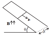
Answer: Let us first divide the magnetic field in the components one is along the inclined plane \(={B} \sin \theta\) and other component of magnetic field is perpendicular the plane \(={B} \cos \theta\). Now, the conductor moves with speed v perpendicular to \({B} \cos \theta\), component of magnetic field. This causes motional emf across two ends of rod, which is
\(
\text { given by }=v(B \cos \theta) d
\)

This makes flow of induced current \(i=\frac{v(B \cos \theta) d}{R}\) where \(R\) is the resistance of rod. Now, current carrying rod experience a magnetic force which is given by \(F_m=i B d\) (horizontally in backward direction). Now, the component of magnetic force parallel to the inclined plane along upward direction
\(
F_{\|}=F_{\mathrm{m}} \cos \theta=i B d \cos \theta=\left(\frac{\nu(B \cos \theta) d}{R}\right) B d \cos \theta
\)
where, \(v=\frac{d x}{d t}\)
Also, the component of weight ( \(m g\) ) parallel to inclined plane along downward direction \(=m g \sin \theta\).
Now, by Newton’s second law of motion
\(
\begin{aligned}
& m \frac{d^2 x}{d t^2}=m g \sin \theta-\frac{B \cos \theta d}{R}\left(\frac{d x}{d t}\right) \times(B d) \cos \theta \\
\Rightarrow & \frac{d v}{d t}=g \sin \theta-\frac{B^2 d^2}{m R}(\cos \theta)^2 v \\
\Rightarrow & \frac{d v}{d t}+\frac{B^2 d^2}{m R}(\cos \theta)^2 v=g \sin \theta
\end{aligned}
\)
But, this is the linear differential equation.
On solving, we get
\(
v=\frac{g \sin \theta}{\frac{B^2 d^2 \cos ^2 \theta}{m R}}+A \exp \left(-\frac{B^2 d^2}{m R}\left(\cos ^2 \theta\right) t\right)
\)
\(A\) is a constant to be determined by initial conditions.
The required expression of velocity as a function of time is given by
\(
=\frac{m g R \sin \theta}{B^2 d^2 \cos ^2 \theta}\left(1-\exp \left(-\frac{B^2 d^2}{m R}\left(\cos ^2 \theta\right) t\right)\right)
\)
Q6.29: Find the current in the sliding rod AB (resistance \(=R\) ) for the arrangement shown in Figure below. \(\mathbf{B}\) is constant and is out of the paper. Parallel wires have no resistance. \(\mathbf{v}\) is constant. Switch \({S}\) is closed at time \(t=0\).

Answer: The conductor of length \(d\) moves with speed \(\mathbf{v}\), perpendicular to magnetic field \(\mathbf{B}\) as shown in figure. This produces motional emf across two ends of rod, which is given by \(=v B d\). Since, switch \(S\) is closed at time \(t=0\). capacitor is charged by this potential difference. Let \(Q(t)\) is charge on the capacitor and current flows from \(A\) to \(B\). Now, the induced current
\(
I==\frac{a Q}{d t}=\frac{v B d}{R}-\frac{Q}{R C}
\)
\(
\begin{aligned}
& \frac{Q}{R C}+\frac{d Q}{d t}=\frac{B v d}{R} \\
& Q+R C \frac{d Q}{d t}=v B C \quad(\text { Let } v B d C=A) \\
& Q+R C \frac{Q}{d t} A \\
& \frac{d Q}{A-Q}=\frac{1}{R C} d t
\end{aligned}
\)
By integrating we have
\(
\begin{aligned}
& \int_0^Q \frac{d Q}{A-Q}=\frac{1}{R C} \int_0^t d t-[\ln (A-Q)-\ln A]=\frac{t}{R C} \\
& \ln \frac{A-Q}{A}=-\frac{t}{R C} \\
& \frac{A-Q}{A}=e^{-t / R C} \\
& Q=A\left(1-e^{-t / R C}\right)
\end{aligned}
\)
Current in the rod,
\(
\begin{aligned}
I & =\frac{d Q}{d t}=\frac{d}{d t}\left[A\left(1-e^{-t / R C}\right)\right] \\
& =-A\left(e^{-t / R C}\right)\left(-\frac{1}{R C}\right) \\
I & =\frac{v B d}{R} e^{-t / R C}
\end{aligned}
\)
Q6.30: Find the current in the sliding rod AB (resistance \(=R\) ) for the arrangement shown in Figure below. \(\mathbf{B}\) is constant and is out of the paper. Parallel wires have no resistance. \(\boldsymbol{v}\) is constant. Switch \(S\) is closed at time \(t=0\).

Answer: This is the similar problem as we discussed above. Here, a conductor of length d moves with speed \(\mathbf{v}\), perpendicular to magnetic field \(\mathbf{B}\) as shown in figure. Due to this an motional emf is induced across two ends of rod \((e=v B d)\). Since, switch \(S\) is closed at time \(t=0\). current start growing in inductor by the potential difference due to motional emf.
By applying KVL in the given circuit, we have
\(
-L \frac{d I}{d t}+v B d=I R \text { or } L \frac{d I}{d t}+I R=v B d
\)
This is the linear differential equation. On solving, we get
\(
I=\frac{\nu B d}{R}+A e^{-R t / 2}
\)
At \(t=0, I=0\)
\(
\Rightarrow \quad A=-\frac{v B d}{R} \Rightarrow I=\frac{v B d}{R}\left(1-e^{-R t / L}\right)
\)
This is the required expression of current.
Q6.31: A metallic ring of mass \(m\) and radius \(l\) (ring being horizontal) is falling under gravity in a region having a magnetic field. If \(z\) is the vertical direction, the z-component of magnetic field is \(B_z=B_o\) \((1+\lambda z)\). If \(R\) is the resistance of the ring and if the ring falls with a velocity \(v\) , find the energy lost in the resistance. If the ring has reached a constant velocity, use the conservation of energy to determine \(v\) in terms of \(m, B, \lambda\) and acceleration due to gravity \(g\).
Answer: The magnetic flux linked with the metallic ring of mass \(m\) and radius \(l\) falling under gravity in a region having a magnetic field whose \(z\)-component of magnetic field is \(B_z=B_0(1+\lambda z)\) is
\(
\phi=B_z\left(\pi l^2\right)=B_0(1+\lambda z)\left(\pi l^2\right)
\)
Applying Faraday’s law of EMI, we have emf induced given by \(\frac{d \phi}{d t}=\) rate of change of flux
Also, by Ohm’s law
\(
B_0\left(\pi l^2\right) \lambda \frac{d z}{d t}=I R
\)
On rearranging the terms, we have \(\quad I=\frac{\pi l^2 B_0 \lambda}{R} v\)
\(
\text { Energy lost/second }=I^2 R=\frac{\left(\pi l^2 \lambda\right)^2 B_0^2 v^2}{R}
\)
This must come from rate of change in \(\mathrm{PE}=m g \frac{d z}{d t}=m g v\)
[as kinetic energy is constant for \(v=\) constant]
Thus,
\(
m g v=\frac{\left(\pi l^2 \lambda B_0\right)^2 v^2}{R} \text { or } v=\frac{m g R}{\left(\pi l^2 \lambda B_0\right)^2}
\)
This is the required expression of velocity.
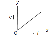
Q6.32: A long solenoid ‘ \(s\) ‘ has ‘ \(n\) ‘ turns per meter, with diameter ‘ \(\alpha\) ‘. At the centre of this coil we place a smaller coil of ‘ \(N\) ‘ turns and diameter ‘ \(b\) ‘ (where \(b<a\) ). If the current in the solenoid increases linearly, with time, what is the induced emf appearing in the smaller coil. Plot graph showing nature of variation in emf, if current varies as a function of \(m t^2+\mathrm{C}\).
Answer: As per data given in the question, magnetic field due to current in solenoid S, \(B=\mu_0 n I\)
Magnetic flux linked with the smaller coil due to this field is
\(\phi=N B A\), where A \(=\) area of smaller coil \(=\pi b^2\)
\(\therefore\) emf induced in the smaller coil,
\(
\begin{aligned}
e & =-\frac{d \phi}{d t}=-\frac{d}{d t}\left(N B \pi b^2\right)=-N \pi b^2 \frac{d}{d t}\left(\mu_0 n I\right) \\
& =-N \pi b^2 \mu_0 n \frac{d I}{d t}
\end{aligned}
\)
As current \(I\) varies as a function of \(\left(t^2+C\right)\), therefore,
\(
\begin{aligned}
e & =-N n \pi \mu_0 b^2 \frac{d}{d t}\left(m t^2+C\right)=-N n \pi \mu_0 b^2(2 m t) \\
& =-\mu_0 N n \pi b^2(2 m t) \dots(i)
\end{aligned}
\)
Negative sign indicates that emf induced oppose the main current in the long solenoid.
\(\text { From (i), }|e| \propto t\)
Hence, the variation of induced emf \(|e|\) with time \(t\) is representedd by a straight line graph as shown in Figure below.