4.5 Magnetic Field on the Axis of a Circular Current Loop
In this section, we shall evaluate the magnetic field due to a circular coil along its axis. The evaluation entails summing up the effect of infinitesimal current elements \((I \mathrm{~d} l)\) mentioned in the previous section. We assume that the current \(I\) is steady and that the evaluation is carried out in free space (i.e., vacuum).
Fig. 4.9 depicts a circular loop carrying a steady current \(I\). The loop is placed in the \(y-z\) plane with its centre at the origin \(O\) and has a radius \(R\). The \(x\)-axis is the axis of the loop. We wish to calculate the magnetic field at the point P on this axis. Let \(x\) be the distance of \(P\) from the centre \(O\) of the loop.
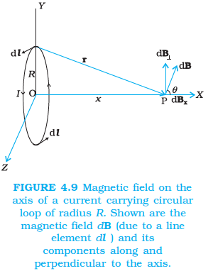
Consider a conducting element \(\mathrm{d} \boldsymbol{l}\) of the loop. This is shown in Fig. 4.9. The magnitude \(d B\) of the magnetic field due to \(\mathrm{d} l\) is given by the Biot-Savart law [Eq. 4.11 (a)],
\(
d B=\frac{\mu_0}{4 \pi} \frac{I|d \boldsymbol{l} \times \mathbf{r}|}{r^3} \dots(4.12)
\)
Now \(r^2=x^2+R^2\). Further, any element of the loop will be perpendicular to the displacement vector from the element to the axial point. For example, the element \(\mathrm{d} \boldsymbol{l}\) in Fig. 4.9 is in the \(y\)-z plane, whereas, the displacement vector \(\mathbf{r}\) from \(\mathrm{d} \boldsymbol{l}\) to the axial point P is in the \(x-y\) plane. Hence \(|d \boldsymbol{l} \times \mathbf{r}|=r d l\). Thus,
\(
\mathrm{d} B=\frac{\mu_0}{4 \pi} \frac{I \mathrm{~d} l}{\left(x^2+R^2\right)} \dots(4.13)
\)
The direction of dB is shown in Fig. 4.9. It is perpendicular to the plane formed by \(\mathrm{d} \boldsymbol{l}\) and \(\mathbf{r}\). It has an \(x\)-component \(\mathrm{d} \mathbf{B}_x\) and a component perpendicular to \(x\)-axis, \(\mathrm{d} \mathbf{B}_{\perp}\). When the components perpendicular to the \(x\)-axis are summed over, they cancel out and we obtain a null result. For example, the \(\mathrm{d} \mathbf{B}_{\perp}\) component due to \(\mathrm{d} l\) is cancelled by the contribution due to the diametrically opposite \(\mathrm{d} \boldsymbol{l}\) element, shown in Fig. 4.9. Thus, only the \(x\)-component survives. The net contribution along \(x\)-direction can be obtained by integrating \(\mathrm{d} B_x=\mathrm{d} B \cos \theta\) over the loop. For Fig. 4.9,
\(
\cos \theta=\frac{R}{\left(x^2+R^2\right)^{1 / 2}} \dots(4.14)
\)
From Eqs. (4.13) and (4.14),
\(
\mathrm{d} B_x=\frac{\mu_0 I \mathrm{~d} l}{4 \pi} \frac{R}{\left(x^2+R^2\right)^{3 / 2}}
\)
The summation of elements \(\mathrm{d} l\) over the loop yields \(2 \pi R\), the circumference of the loop. Thus, the magnetic field at P due to entire circular loop is
\(
\mathbf{B}=B_x \hat{\mathbf{i}}=\frac{\mu_0 I R^2}{2\left(x^2+R^2\right)^{3 / 2}} \hat{\mathbf{i}} \dots(4.15)
\)
As a special case of the above result, we may obtain the field at the centre of the loop. Here \(x=0\), and we obtain,
\(
\mathbf{B}_0=\frac{\mu_0 I}{2 R} \hat{\mathbf{i}} \dots(4.16)
\)
The magnetic field lines due to a circular wire form closed loops and are shown in Fig. 4.10. The direction of the magnetic field is given by (another) right-hand thumb rule stated below:
Curl the palm of your right hand around the circular wire with the fingers pointing in the direction of the current. The right-hand thumb gives the direction of the magnetic field.

Example 4.6: A straight wire carrying a current of 12 A is bent into a semi-circular arc of radius 2.0 cm as shown in Fig. 4.11(a). Consider the magnetic field \(\mathbf{B}\) at the centre of the arc. (a) What is the magnetic field due to the straight segments? (b) In what way the contribution to B from the semicircle differs from that of a circular loop, and in what way does it resemble? (c) Would your answer be different if the wire were bent into a semi-circular arc of the same radius but in the opposite way as shown in Fig. 4.11 (b)?

Solution: (a) \(\mathrm{d} \mathbf{l}\) and \(\mathbf{r}\) for each element of the straight segments are parallel. Therefore, \(\mathrm{d} \boldsymbol{l} \times \mathbf{r}=0\). Straight segments do not contribute to \(|\mathbf{B}|\).
(b) For all segments of the semicircular arc, \(\mathrm{d} \boldsymbol{l} \times \mathbf{r}\) are all parallel to each other (into the plane of the paper). All such contributions add up in magnitude. Hence, the direction of \(\mathbf{B}\) for a semicircular arc is given by the right-hand rule, and the magnitude is half that of a circular loop. Thus \(\mathbf{B}\) is \(1.9 \times 10^{-4} \mathrm{~T}\) normal to the plane of the paper going into it.
(c) Same magnitude of \(\mathbf{B}\) but opposite in direction to that in (b).
Example 4.7: Consider a tightly wound 100 turn coil of radius 10 cm, carrying a current of 1 A. What is the magnitude of the magnetic field at the centre of the coil?
Solution: Since the coil is tightly wound, we may take each circular element to have the same radius \(R=10 \mathrm{~cm}=0.1 \mathrm{~m}\). The number of turns \(N=100\). The magnitude of the magnetic field is,
\(
B=\frac{\mu_0 N I}{2 R}=\frac{4 \pi \times 10^{-7} \times 10^2 \times 1}{2 \times 10^{-1}}=2 \pi \times 10^{-4}=6.28 \times 10^{-4} \mathrm{~T}
\)