JEE Physics Test Series Quiz-7
Quiz Summary
0 of 50 Questions completed
Questions:
Information
You have already completed the quiz before. Hence you can not start it again.
Quiz is loading…
You must sign in or sign up to start the quiz.
You must first complete the following:
Results
Results
0 of 50 Questions answered correctly
Your time:
Time has elapsed
You have reached 0 of 0 point(s), (0)
Earned Point(s): 0 of 0, (0)
0 Essay(s) Pending (Possible Point(s): 0)
Categories
- Not categorized 0%
- 1
- 2
- 3
- 4
- 5
- 6
- 7
- 8
- 9
- 10
- 11
- 12
- 13
- 14
- 15
- 16
- 17
- 18
- 19
- 20
- 21
- 22
- 23
- 24
- 25
- 26
- 27
- 28
- 29
- 30
- 31
- 32
- 33
- 34
- 35
- 36
- 37
- 38
- 39
- 40
- 41
- 42
- 43
- 44
- 45
- 46
- 47
- 48
- 49
- 50
- Current
- Review
- Answered
- Correct
- Incorrect
-
Question 1 of 50
1. Question
1 point(s)A small bar magnet is moved through a coil at a constant speed from one end to the other. Which of the following series of observations will be seen on the galvanometer G attached across the coil?

Three positions shown describe (1) the magnet’s entry (2) the magnet is completely inside and (3) the magnet’s exit.
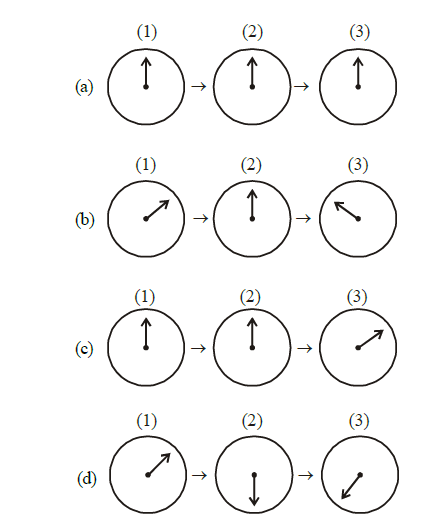 CorrectIncorrect
 -
Question 2 of 50
2. Question
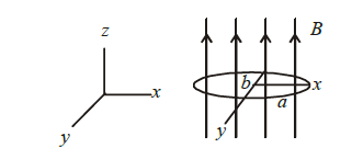
1 point(s)An elliptical loop having resistance \(R\), of semi-major axis \(a\), and semi-minor axis \(b\) is placed in a magnetic field as shown in the figure. If the loop is rotated about the \(x\)-axis with angular frequency \(\omega\), the average power loss in the loop due to Joule heating is :
 CorrectIncorrect
 -
Question 3 of 50
3. Question
1 point(s)A uniform magnetic field \(B\) exists in a direction perpendicular to the plane of a square loop made of a metal wire. The wire has a diameter of \(4 \mathrm{~mm}\) and a total length of \(30 \mathrm{~cm}\). The magnetic field changes with time at a steady rate \(d B / d t=0.032 \mathrm{Ts}^{-1}\). The induced current in the loop is close to (Resistivity of the metal wire is \(\left.1.23 \times 10^{-8} \Omega \mathrm{m}\right)\)
CorrectIncorrect -
Question 4 of 50
4. Question
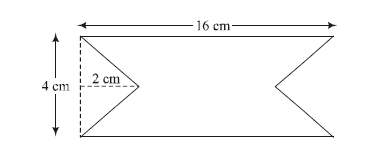
1 point(s)At time \(t=0\) magnetic field of 1000 Gauss is passing perpendicularly through the area defined by the closed loop shown in the figure. If the magnetic field reduces linearly to 500 Gauss, in the next \(5 \mathrm{~s}\), then induced EMF in the loop is:
 CorrectIncorrect
 -
Question 5 of 50
5. Question
1 point(s)Consider a circular coil of wire carrying constant current \(I\), forming a magnetic dipole. The magnetic flux through an infinite plane that contains the circular coil and excluding the circular coil area is given by \(\phi_i\). The magnetic flux through the area of the circular coil area is given by \(\phi_0\). Which of the following option is correct?
CorrectIncorrect -
Question 6 of 50
6. Question
1 point(s)A long solenoid of radius \(R\) carries a time \((t)\) – dependent current \(I(t)=I_0 t(1-t)\). A ring of radius \(2 R\) is placed coaxially near its middle. During the time interval \(0 \leq t \leq 1\), the induced current \(\left(I_R\right)\) and the induced \(\operatorname{EMF}\left(V_R\right)\) in the ring change as:
CorrectIncorrect -
Question 7 of 50
7. Question
1 point(s)A planar loop of wire rotates in a uniform magnetic field. Initially, at \(t=0\), the plane of the loop is perpendicular to the magnetic field. If it rotates with a period of \(10 \mathrm{~s}\) about an axis in its plane then the magnitude of induced emf will be maximum and minimum, respectively at:
CorrectIncorrect -
Question 8 of 50
8. Question
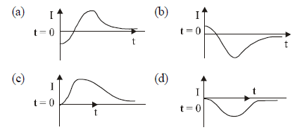
1 point(s)A very long solenoid of radius \(R\) is carrying current \(\mathrm{I}(\mathrm{t})=\mathrm{kte}^{-\mathrm{at}}(k>0)\), as a function of time \((t \geq 0)\). Counterclockwise current is taken to be positive. A circular conducting coil of radius \(2 \mathrm{R}\) is placed in the equatorial plane of the solenoid and concentric with the solenoid. The current induced in the outer coil is correctly depicted, as a function of time, by:
 CorrectIncorrect
 -
Question 9 of 50
9. Question
1 point(s)The self-induced emf of a coil is 25 volts. When the current in it is changed at uniform rate from \(10 \mathrm{~A}\) to 25 \(A\) in 1s, the change in the energy of the inductance is:
CorrectIncorrect -
Question 10 of 50
10. Question
1 point(s)A conducting circular loop made of a thin wire has area \(3.5 \times 10^{-3} \mathrm{~m}^2\) and resistance \(10 \Omega\). It is placed perpendicular to a time-dependent magnetic field \(\mathrm{B}(\mathrm{t})=(0.4 \mathrm{~T}) \sin (50 \pi \mathrm{t})\). The net charge flowing through the loop during \(t=0\) \(\mathrm{s}\) and \(\mathrm{t}=10 \mathrm{~ms}\) is close to:
CorrectIncorrect -
Question 11 of 50
11. Question
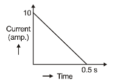
1 point(s)In a coil of resistance \(100 \Omega\), a current is induced by changing the magnetic flux through it as shown in the figure. The magnitude of change in flux through the coil is
 CorrectIncorrect
 -
Question 12 of 50
12. Question
1 point(s)A conducting metal circular-wire-loop of radius \(r\) is placed perpendicular to a magnetic field which varies with time as \(\mathrm{B}=\mathrm{B}_0 \mathrm{e}^{-t / \tau} \text {, where } \mathrm{B}_0 \text { and } \tau \text { are constants, at time } \mathrm{t}=0 \text {. }\) If the resistance of the loop is \(\mathrm{R}\) then the heat generated in the loop after a long time \((t \rightarrow \infty)\) is :
CorrectIncorrect -
Question 13 of 50
13. Question
1 point(s)When current in a coil changes from \(5 \mathrm{~A}\) to \(2 \mathrm{~A}\) in \(0.1 \mathrm{~s}\), the average voltage of \(50 \mathrm{~V}\) is produced. The self-inductance of the coil is:
CorrectIncorrect -
Question 14 of 50
14. Question
1 point(s)The figure shows a circular area of radius \(\mathrm{R}\) where a uniform magnetic field \(\vec{B}\) is going into the plane of the paper and increasing in magnitude at a constant rate.
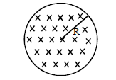
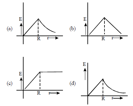
In that case, which of the following graphs, drawn schematically, correctly shows the variation of the induced electric field \(\mathrm{E}(\mathrm{r})\)?
 CorrectIncorrect
 -
Question 15 of 50
15. Question
1 point(s)A circular loop of radius \(0.3 \mathrm{~cm}\) lies parallel to a much bigger circular loop of radius \(20 \mathrm{~cm}\). The centre of the small loop is on the axis of the bigger loop. The distance between their centres is \(15 \mathrm{~cm}\). If a current of \(2.0 \mathrm{~A}\) flows through the smaller loop, then the flux linked with the bigger loop is
CorrectIncorrect -
Question 16 of 50
16. Question
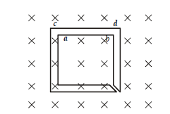
1 point(s)The figure shows certain wire segments joined together to form a coplanar loop. The loop is placed in a perpendicular magnetic field in the direction going into the plane of the figure. The magnitude of the field increases with time. \(I_1\) and \(I_2\) are the currents in the segments \(\mathbf{a b}\) and \(\mathbf{c d}\). Then,
 CorrectIncorrect
 -
Question 17 of 50
17. Question
1 point(s)A small bar magnet is being slowly inserted with constant velocity inside a solenoid as shown in the figure. Which graph best represents the relationship between emf induced with time
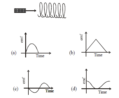 CorrectIncorrect
 -
Question 18 of 50
18. Question
1 point(s)A thin circular ring of area \(A\) is held perpendicular to a uniform magnetic field of induction \(B\). \(A\) small cut is made in the ring and a galvanometer is connected across the ends such that the total resistance of the circuit is \(R\). When the ring is suddenly squeezed to zero area, the charge flowing through the galvanometer is
CorrectIncorrect -
Question 19 of 50
19. Question
1 point(s)A series \(\mathrm{R}-\mathrm{C}\) combination is connected to an \(\mathrm{AC}\) voltage of angular frequency \(\omega=500 \mathrm{radian} / \mathrm{s}\). If the impedance of the R-C circuit is \(R \sqrt{1.25}\), the time constant (in milliseconds) of the circuit is
CorrectIncorrect -
Question 20 of 50
20. Question
1 point(s)The figure shows a square loop \(L\) of side \(5 \mathrm{~cm}\) which is connected to a network of resistances. The whole setup is moving towards the right with a constant speed of \(1 \mathrm{~cm} \mathrm{~s}^{-1}\). At some instant, a part of \(\mathrm{L}\) is in a uniform magnetic field of \(1 \mathrm{~T}\), perpendicular to the plane of the loop. If the resistance of \(L\) is \(1.7 \Omega\), the current in the loop at that instant will be close to :
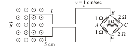 CorrectIncorrect
 -
Question 21 of 50
21. Question
1 point(s)The total number of turns and cross-section area in a solenoid is fixed. However, its length \(L\) is varied by adjusting the separation between windings. The inductance of solenoid will be proportional to:
CorrectIncorrect -
Question 22 of 50
22. Question
1 point(s)A \(10 \mathrm{~m}\) long horizontal wire extends from North East to South West. It is falling with a speed of \(5.0 \mathrm{~ms}^{-1}\), at right angles to the horizontal component of the earth’s magnetic field, of \(0.3 \times 10^{-4} \mathrm{~Wb} / \mathrm{m}^2\). The value of the induced emf in wire is :
CorrectIncorrect -
Question 23 of 50
23. Question
1 point(s)A copper wire is wound on a wooden frame, whose shape is that of an equilateral triangle. If the linear dimension of each side of the frame is increased by a factor of 3, keeping the number of turns of the coil per unit length of the frame the same, then the self-inductance of the coil:
CorrectIncorrect -
Question 24 of 50
24. Question
1 point(s)An insulating thin rod of length \(l\) has a linear charge density \(\rho(x)=\rho_0 \frac{x}{l}\) on it. The rod is rotated about an axis passing through the origin \((x=0)\) and perpendicular to the rod. If the rod makes \(\mathrm{n}\) rotations per second, then the time-averaged magnetic moment of the rod is:
CorrectIncorrect -
Question 25 of 50
25. Question
1 point(s)A conducting square loop of side \(L\) and resistance \(R\) moves in its plane with a uniform velocity \(v\) perpendicular to one of its sides. A magnetic induction \(B\), constant in time and space, pointing perpendicular and into the plane of the loop exists everywhere. The current induced in the loop is:
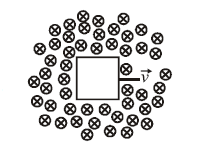 CorrectIncorrect
 -
Question 26 of 50
26. Question
1 point(s)An alternating voltage \(v(t)=220 \sin 100 \pi t\) volt is applied to a purely resistive load of \(50 \Omega\). The time taken for the current to rise from half of the peak value to the peak value is:
CorrectIncorrect -
Question 27 of 50
27. Question
1 point(s)A sinusoidal voltage \(V(t)=100 \sin (500 t)\) is applied across a pure inductance of \(\mathrm{L}=0.02 \mathrm{H}\). The current through the coil is:
CorrectIncorrect -
Question 28 of 50
28. Question
1 point(s)An AC circuit has \(R=100 \Omega, C=2 \mu \mathrm{F}\) and \(L=80 \mathrm{mH}\), connected in series. The quality factor of the circuit is :
CorrectIncorrect -
Question 29 of 50
29. Question
1 point(s)A series \(L-R\) circuit is connected to a battery of emf \(V\). If the circuit is switched on at \(t=0\), then the time at which the energy stored in the inductor reaches \(\left(\frac{1}{n}\right)\) times of its maximum value, is:
CorrectIncorrect -
Question 30 of 50
30. Question
1 point(s)A \(750 \mathrm{~Hz}, 20 \mathrm{~V}\) (rms) source is connected to a resistance of \(100 \Omega\), an inductance of \(0.1803 \mathrm{H}\) and a capacitance of 10\(\mu \mathrm{F}\) all in series. The time in which the resistance (heat capacity \(2 \mathrm{~J} /{ }^{\circ} \mathrm{C}\) ) will get heated by \(10^{\circ} \mathrm{C}\). (assume no loss of heat to the surroundings) is close to :
CorrectIncorrect -
Question 31 of 50
31. Question
1 point(s)An inductance coil has a reactance of \(100 \Omega\). When an AC signal of frequency \(1000 \mathrm{~Hz}\) is applied to the coil, the applied voltage leads the current by \(45^{\circ}\). The self-inductance of the coil is :
CorrectIncorrect -
Question 32 of 50
32. Question
1 point(s)Consider the LR circuit shown in the figure. If the switch \(\mathrm{S}\) is closed at \(\mathrm{t}=0\) then the amount of charge that passes through the battery between \(\mathrm{t}=0\) and \(t=\frac{L}{R}\) is :
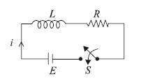 CorrectIncorrect
 -
Question 33 of 50
33. Question
1 point(s)A 20 Henry inductor coil is connected to a \(10 \mathrm{ohm}\) resistance in series as shown in the figure. The time at which the rate of dissipation of energy (Joule’s heat) across the resistance is equal to the rate at which magnetic energy is stored in the inductor is :
 CorrectIncorrect
 -
Question 34 of 50
34. Question
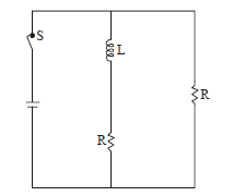
1 point(s)In the figure shown, a circuit contains two identical resistors with resistance \(R=5 \Omega\) and an inductance with \(\mathrm{L}\) \(=2 \mathrm{mH}\). An ideal battery of \(15 \mathrm{~V}\) is connected in the circuit. What will be the current through the battery long after the switch is closed?
 CorrectIncorrect
 -
Question 35 of 50
35. Question
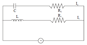
1 point(s)In the below circuit, \(\mathrm{C}=\frac{\sqrt{3}}{2} \mu \mathrm{F}, \mathrm{R}_2=20 \Omega, \mathrm{L}=\frac{\sqrt{3}}{10} \mathrm{H}\) and \(R_1=10 \Omega \text {. Current in } L-R_1 \text { path is } I_1 \text { and in C- } R_2 \text { path it is }\) \(I_2\). The voltage of A.C source is given by, \(V=200 \sqrt{2} \sin (100 t) \text { volts. The phase difference between } I_1 \text { and } I_2 \text { is: }\)
 CorrectIncorrect
 -
Question 36 of 50
36. Question
1 point(s)In the circuit shown,
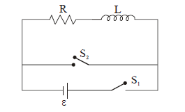
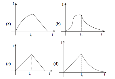
the switch \(\mathrm{S}_1\) is closed at time \(\mathrm{t}=0\) and the switch \(\mathrm{S}_2\) is kept open. At some later time \(\left(t_0\right)\), the switch \(S_1\) is opened and \(\mathrm{S}_2\) is closed. the behaviour of the current \(\mathrm{I}\) as a function of time ‘ \(t\) ‘ is given by:
 CorrectIncorrect
 -
Question 37 of 50
37. Question
1 point(s)In \(\mathrm{LC}\) circuit the inductance \(\mathrm{L}=40 \mathrm{mH}\) and capacitance \(\mathrm{C}\) \(=100.00 \mu \mathrm{F}\). If a voltage \(\mathrm{V}(t)=10 \sin (314 t)\) is applied to the circuit, the current in the circuit is given as:
CorrectIncorrect -
Question 38 of 50
38. Question
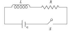
1 point(s)As shown in the figure, a battery of emf \(\in\) is connected to an inductor \(L\) and resistance \(R\) in series. The switch is closed at \(t=0\). The total charge that flows from the battery, between \(t\) \(=0\) and \(t=t_c\left(t_c\right.\) is the time constant of the circuit \()\) is:
 CorrectIncorrect
 -
Question 39 of 50
39. Question
1 point(s)A LCR circuit behaves like a damped harmonic oscillator. Comparing it with a physical spring-mass damped oscillator having damping constant ‘ \(b\) ‘, the correct equivalence would be:
CorrectIncorrect -
Question 40 of 50
40. Question
1 point(s)An emf of \(20 \mathrm{~V}\) is applied at time \(t=0\) to a circuit containing in series \(10 \mathrm{mH}\) inductor and \(5 \Omega\) resistor. The ratio of the currents at time \(t=\infty\) and at \(t=40 \mathrm{~s}\) is close to: \(\text { (Take } \left.e^2=7.389\right)\)
CorrectIncorrect -
Question 41 of 50
41. Question
1 point(s)In an a.c. circuit, the instantaneous e.m.f. and current are given by
\(
\begin{aligned}
& e=100 \sin 30 t \\
& i=20 \sin \left(30 \mathrm{t}-\frac{\pi}{4}\right)
\end{aligned}
\)
In one cycle of a.c., the average power consumed by the circuit and the wattless current are, respectively.CorrectIncorrect -
Question 42 of 50
42. Question
1 point(s)For an RLC circuit driven with a voltage of amplitude \(v_{\mathrm{m}}\) and frequency \(\omega_0=\frac{1}{\sqrt{\mathrm{LC}}}\) the current exhibits resonance. The quality factor, \(\)Q\(\) is given by:
CorrectIncorrect -
Question 43 of 50
43. Question
1 point(s)A sinusoidal voltage of peak value \(283 \mathrm{~V}\) and angular frequency \(320 / \mathrm{s}\) is applied to a series LCR circuit. Given that \(\mathrm{R}=5 \Omega, \mathrm{L}=25 \mathrm{mH}\) and \(\mathrm{C}=1000 \mu \mathrm{F}\). The total impedance, and phase difference between the voltage across the source and the current will respectively be :
CorrectIncorrect -
Question 44 of 50
44. Question
1 point(s)An arc lamp requires a direct current of \(10 \mathrm{~A}\) at \(80 \mathrm{~V}\) to function. If it is connected to a \(220 \mathrm{~V}\) (rms), \(50 \mathrm{~Hz} \mathrm{~AC}\) supply, the series inductor needed for it to work is close to :
CorrectIncorrect -
Question 45 of 50
45. Question
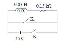
1 point(s)An inductor \((L=0.03 \mathrm{~H})\) and a resistor \((\mathrm{R}=0.15 \mathrm{k} \Omega)\) are connected in series to a battery of \(15 \mathrm{~V}\) emf in a circuit shown below. The key \(\mathrm{K}_1\) has been kept closed for a long time. Then at \(t=0, K_1\) is opened and key \(K_2\) is closed simultaneously. At \(\mathrm{t}=1 \mathrm{~ms}\), the current in the circuit will be: \(\left(e^5 \cong 150\right)\)
 CorrectIncorrect
 -
Question 46 of 50
46. Question
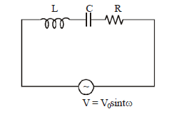
1 point(s)For the LCR circuit, shown here, the current is observed to lead the applied voltage. An additional capacitor C’, when joined with the capacitor \(\mathrm{C}\) present in the circuit, makes the power factor of the circuit unity. The capacitor \(\mathrm{C}^{\prime}\), must have been connected in :
 CorrectIncorrect
 -
Question 47 of 50
47. Question
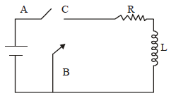
1 point(s)In the circuit shown here, the point ‘ \(\mathrm{C}\) ‘ is kept connected to point ‘ \(\mathrm{A}\) ‘ till the current flowing through the circuit becomes constant. Afterward, suddenly, point ‘ \(C\) ‘ is disconnected from point ‘ \(A\) ‘ and connected to point ‘ \(B\) ‘ at time \(t=0\). Ratio of the voltage across resistance and the inductor at \(t=L / R\) will be equal to:
 CorrectIncorrect
 -
Question 48 of 50
48. Question
1 point(s)When the rms voltages \(V_L, V_C\) and \(V_R\) are measured respectively across the inductor \(\mathrm{L}\), the capacitor \(\mathrm{C}\) and the resistor \(\mathrm{R}\) in a series \(\mathrm{LCR}\) circuit connected to an \(\mathrm{AC}\) source, it is found that the ratio \(V_L: V_C: V_R=1: 2: 3\). If the rms voltage of the \(A C\) sources is \(100 \mathrm{~V}\), the \(V_R\) is close to:
CorrectIncorrect -
Question 49 of 50
49. Question
1 point(s)A series LR circuit is connected to an ac source of frequency \(\omega\) and the inductive reactance is equal to \(2 R[latex]. A capacitance of capacitive reactance equal to [latex]R\) is added in series with \(L\) and \(R\). The ratio of the new power factor to the old one is :
CorrectIncorrect -
Question 50 of 50
50. Question
1 point(s)An \(\mathrm{AC}\) voltage source of variable angular frequency \(\omega\) and fixed amplitude \(V_0\) is connected in series with a capacitance \(C\) and an electric bulb of resistance \(R\) (inductance zero). When \(\omega\) is increased
CorrectIncorrect